[0022] The technical solutions in the embodiments of the present invention will be clearly and completely described below with reference to the accompanying drawings in the embodiments of the present invention.
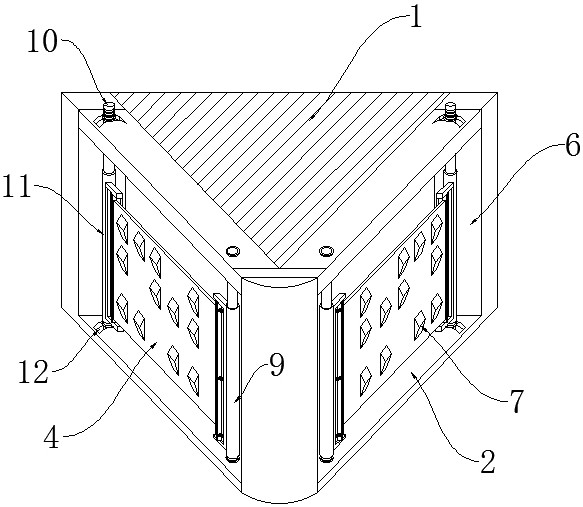
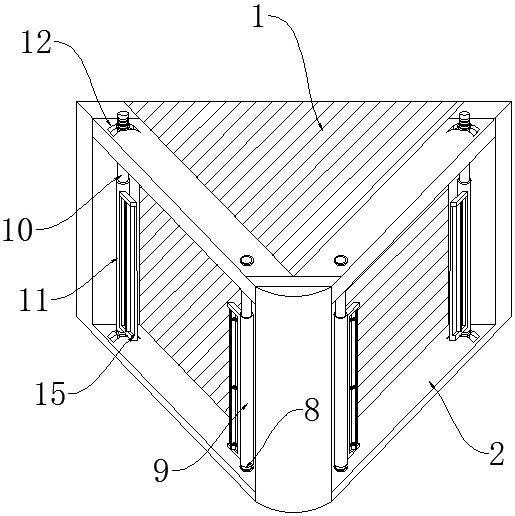
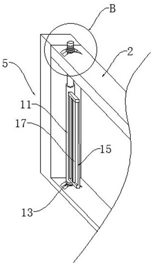
[0023] like Figure 1-6 As shown, the present invention provides a technical solution: a prism structure with unevenly distributed convex structures, comprising a prism body 1, two sets of extension frames 2, two sets of positioning components 3, two sets of convex plates 4 and two sets of adjustment components 5. The two sets of extension frames 2 are integrally pressed on the emitting surfaces on both sides of the prism body 1. The extension frames 2 are provided with a rectangular mounting area 6 correspondingly. In the side rectangular installation area 6, the positioning assembly 3 is correspondingly installed on the adjusting assembly 5, the convex plate 4 is correspondingly installed in the positioning assembly 3, and the convex plate 4 and the emitting surfaces of the two side walls of the prism body 1 interval setting.
[0024] In this embodiment, specifically, the raised plate 4 is made of transparent material as a whole, and a plurality of groups of raised blocks 7 are unevenly distributed on the side wall of the raised plate 4 .
[0025] In this embodiment, specifically: the adjustment assembly 5 includes a No. 1 positioning rod 8, a No. 1 positioning sleeve 9, a No. 2 positioning rod 10, a No. 2 positioning sleeve 11 and two sets of fine-tuning parts. The rod 8 is rotatably installed on one side of the rectangular installation area 6, the No. 1 positioning sleeve 9 is correspondingly sleeved outside the No. 1 positioning rod 8, and the No. 2 positioning rod 10 is slidably installed on the other side of the rectangular installation area 6 , the No. 2 positioning sleeve 11 is correspondingly installed on the outside of the No. 2 positioning rod 10, and the two sets of fine-tuning parts are correspondingly installed on the top and bottom ends of the extension frame 2. The staff can push the No. 2 positioning rod 10 to slide, so that the convex The lifting plate 4 is inclined following the No. 1 positioning rod 8, which realizes the adjustment of the inclination and the inclination of the angle of the convex plate 4, and further increases the overall refraction angle.
[0026] In this embodiment, specifically: the No. 1 positioning sleeve 9 and the No. 2 positioning sleeve 11 have the same size, and the No. 1 positioning sleeve 9 and the No. 2 positioning sleeve 11 have a cylindrical structure as a whole.
[0027] In this embodiment, specifically: the fine-tuning part includes an arc-shaped track 12, two sets of sliding plates 13 and two sets of fastening bolts 14, the arc-shaped track 12 runs through the top and bottom ends of the extension frame 2, and two The top and bottom ends of the No. 1 positioning rod 10 extend through the arc-shaped track 12 correspondingly, and the outer surfaces of the top and bottom ends of the No. 2 positioning rod 10 are provided with external thread areas. The two sets of sliding plates 13 are correspondingly sleeved on the No. 2 positioning rod Outside the positioning rod 10, and the sliding plate 13 is slidingly attached to the arc-shaped track 12, two sets of the fastening bolts 14 are correspondingly screwed and sleeved on the top and bottom ends of the second positioning rod 10, and the arc-shaped track 12 is used to realize In order to adjust the limit sliding of the No. 2 positioning rod 10, when the angle adjustment of the raised plate 4 is completed, the staff rotates the fastening bolt 14, and uses the fastening bolt 14 to connect with the external thread area of the No. 2 positioning rod 10. Next, the positioning and fixing of the raised plate 4 is realized.
[0028] In this embodiment, specifically: the positioning assembly 3 includes two sets of positioning plates 15 , two sets of positioning grooves 16 and two sets of clamping parts, and the two sets of positioning plates 15 are correspondingly installed in a No. 1 positioning sleeve 9 . 2. On the inner side of the No. 2 positioning sleeve 11, the positioning groove 16 is correspondingly opened on the top end side of the positioning plate 15, the clamping portion is correspondingly installed on the positioning plate 15 and is located in the positioning groove 16, and the back of the raised plate 4 is two The side corresponding to the positioning plate 15 is engaged and fixed, and the positioning groove 16 is used to realize the storage and fixation of the raised plate 4 .
[0029] In this embodiment, specifically: the clamping portion includes an adjustment plate 17 and a plurality of sets of positioning springs 18 , the adjustment plate 17 is slidably installed in the positioning groove 16 , and the adjustment plate 17 is on both sides of the raised plate 4 . The walls are in contact with each other, and multiple sets of the positioning springs 18 are evenly distributed between the inner wall of the positioning groove 16 and the adjustment plate 17. Under the elastic driving of the positioning spring 18, the adjustment plate 17 is slid left and right in the positioning groove 16 and adjusted to achieve In order to dynamically adjust the inner space of the positioning groove 16, the raised plates 4 of different sizes can be positioned and fixed synchronously, which improves the overall adaptability of the equipment.
[0030]Working principle, when in use, firstly, two sets of extension frames 2 are integrally pressed on the emission surfaces on both sides of the prism body 1, and the rectangular installation area 6 is used to facilitate the staff to store and install the raised plate 4 later, and different types of The protruding plate 4 is replaced, which improves the use effect of the prism body 1. By providing the positioning assembly 3, the staff places the protruding plate 4 in the rectangular installation area 6 correspondingly. 15 corresponding to the clamping and fixing, the positioning groove 16 is used to realize the storage and fixation of the convex plate 4, which ensures the installation stability of the convex plate 4, and then the light is refracted through the convex plate 4 and the prism body 1, which ensures the subsequent The precision of light refraction, and with the assistance of the clamping part and the elastic drive of the positioning spring 18, the adjustment plate 17 can be slid left and right in the positioning groove 16 to adjust, so as to realize the dynamic adjustment of the internal space of the positioning groove 16, which can be synchronized. The positioning and fixing of the raised plates 4 of different sizes improves the overall adaptability of the equipment. At the same time, the elastic push of the positioning spring 18 makes the adjustment plate 17 abut against the side walls of the raised plates 4, which strengthens the raised plates. 4. The installation is stable. By providing the adjustment assembly 5, since the No. 1 positioning rod 8 is rotatably connected with the rectangular installation area 6, and the No. 2 positioning rod 10 rotates following the arc track 12 in the rectangular installation area 6, when the staff uses it , the No. 2 positioning rod 10 can be pushed to slide, so that the convex plate 4 follows the No. 1 positioning rod 8 to incline, realizing the inclination and camber adjustment of the angle of the convex plate 4, and further increasing the overall refraction angle, which can be used for The staff adjusts the use, and with the assistance of the fine-tuning part, the arc track 12 is used to realize the limit sliding adjustment of the No. 2 positioning rod 10. When the angle adjustment of the raised plate 4 is completed, the staff turns the fastening bolt 14. , the positioning and fixing of the raised plate 4 is realized by using the fastening bolt 14 to be connected with the external thread area of the No. 2 positioning rod 10 by screwing.
[0031] Although embodiments of the present invention have been shown and described, it will be understood by those skilled in the art that various changes, modifications, and substitutions can be made in these embodiments without departing from the principle and spirit of the invention and modifications, the scope of the present invention is defined by the appended claims and their equivalents.