
Common line of swing shear blanking line and laser blanking line

A technology of blanking line and laser, which is applied in the field of plate processing, can solve the problems of reducing processing efficiency, reducing effect, and poor processing accuracy of the production line, so as to improve the overall adaptability, increase diversity, and reduce investment costs.

Pending Publication Date: 2021-01-29
岳正激光科技(常熟)有限公司
View PDF0 Cites 0 Cited by
  • Summary
  • Abstract
  • Description
  • Claims
  • Application Information

AI Technical Summary

Problems solved by technology

With the gradual development of the domestic automobile industry towards high-end automobiles, more and more automobile manufacturers adopt automatic uncoiling and blanking lines. The purpose is to improve product quality, material utilization and production efficiency. Most of them use the pendulum shear blanking line and the laser blanking line to form their own production systems, and the two processing methods are not integrated and connected in series. Therefore, in the traditional processing, the overall processing accuracy of the production line is poor, and it is impossible to control the two processing methods. Advantages are integrated and complemented, reducing the overall processing effect
[0003] The existing technology has the following disadvantages: when the traditional production cutting line is processed, most of them use the pendulum shear blanking line and the laser blanking line to form a production system respectively, and the two processing methods are not integrated and connected in series. Therefore, in the traditional During processing, the overall processing accuracy of the production line is poor, and the advantages of the two cannot be integrated and complemented, which reduces the overall processing effect and reduces the overall processing efficiency

Method used


Image

  • Common line of swing shear blanking line and laser blanking line
  • Common line of swing shear blanking line and laser blanking line
  • Common line of swing shear blanking line and laser blanking line

Examples


Embodiment Construction

[0017] The following will clearly and completely describe the technical solutions in the embodiments of the present invention with reference to the drawings in the embodiments of the present invention.

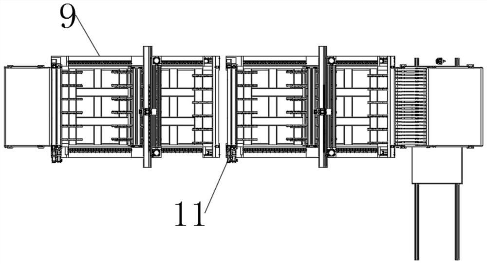
[0018] Such as Figure 1-3 As shown, the present invention provides a technical solution: pendulum shear blanking line and laser blanking line are collinear, including workbench 1, feeding assembly, No. 1 cutting assembly and No. 2 cutting assembly, and the feeding assembly is installed on workbench 1 On the surface, the No. 1 cutting assembly is matched and installed on one side of the feeding assembly, the No. 2 cutting assembly is installed on the side of the No. 1 cutting assembly, and the No. 1 cutting assembly is matched with the No. 2 cutting assembly.

[0019] The feeding assembly includes an uncoiler 2, a pinch roller 3, a straightener 4, a looper 5, and a servo feed roller 6. The uncoiler 2 is installed on one side of the upper surface of the workbench 1, and the pin...


PUM


Abstract

The invention discloses a common line of a swing shear blanking line and laser blanking line. The common line comprises a workbench, a feeding assembly, a first cutting assembly and a second cutting assembly, and the feeding assembly is installed on the upper surface of the workbench; the first cutting assembly is installed on one side of the feeding assembly in a matched mode, and the second cutting assembly is installed on one side of the first cutting assembly; and the first cutting assembly is matched and connected with the second cutting assembly. According to the production line, a swingshearing machine and a laser cutting machine are connected in series for machining, and the two blanking lines are combined; the advantages of the two blanking lines are utilized for different products respectively, and the two blanking lines make good for deficiency; cutting production of plates in various shapes can be met, and other devices can be shared; two original production lines are combined into one production line, and the functions and capacities of the two production lines are achieved through one production line; the efficiency and the product diversity are both achieved, and the investment cost is greatly reduced; and the overall production and machining capacity is improved.

Description

technical field [0001] The invention relates to the related technical field of sheet material processing, in particular to the collinear pendulum shear blanking line and laser blanking line. Background technique [0002] The uncoiling blanking line is a plate processing equipment suitable for uncoiling, cleaning and oiling, leveling, blanking and stacking of surface covering coils in industries such as automobiles and steel plate distribution. It has been widely used in automobile factories in developed countries. use. With the gradual development of the domestic automobile industry towards high-end automobiles, more and more automobile manufacturers adopt automatic uncoiling and blanking lines. The purpose is to improve product quality, material utilization and production efficiency. Most of them use the pendulum shear blanking line and the laser blanking line to form their own production systems, and the two processing methods are not integrated and connected in series. T...

Claims


Application Information

Patent Timeline
IPC IPC(8): B23P23/06
CPCB23P23/06
Inventor 戴秋连保琳
Owner 岳正激光科技(常熟)有限公司
Learn More