Needle having a safety mechanism

A safety mechanism and safe technology, applied in the field of needle components, can solve problems such as stabbing users, needle rebound, and users being exposed to dangerous drugs

Active Publication Date: 2021-08-17
POLY MEDICURE
View PDF15 Cites 0 Cited by
  • Summary
  • Abstract
  • Description
  • Claims
  • Application Information

AI Technical Summary

Problems solved by technology

The force required to withdraw the needle from the implant port's self-sealing septum can cause the needle to kick back and injure the user
This may result in transmission of bloodborne pathogens to the user
Additionally, it exposes users to dangerous drugs

Method used


Image

  • Needle having a safety mechanism
  • Needle having a safety mechanism
  • Needle having a safety mechanism

Examples


Embodiment Construction

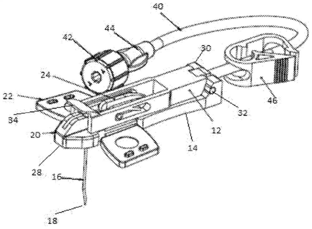
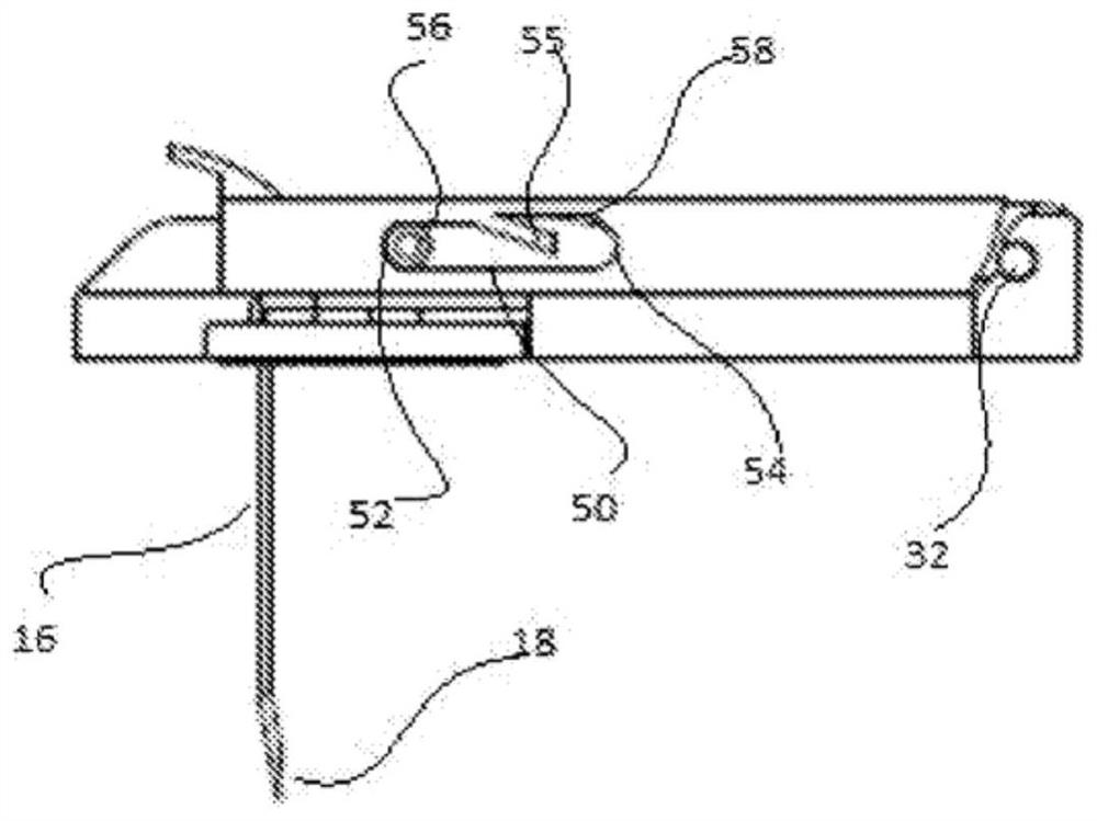
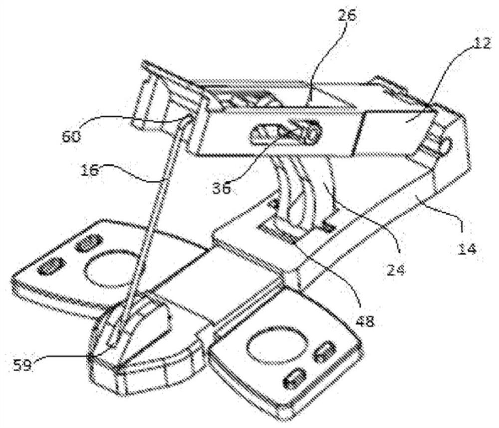
[0031] Embodiments of the presently disclosed invention will now be described in detail with reference to the drawings, wherein like reference numerals indicate like or corresponding elements. In the drawings and description, the terms "proximal", "bottom", "downward" or "lower" refer to the portion of the device that is closest to the practitioner using the device and away from the device when the device is in use in normal operation. Use the device in relation to the furthest position from the patient. Conversely, the terms "distal", "top", "upper" or "upper" refer to the side of the device that is furthest from the clinician using the device and closest to the device in relation to use of the device when the device is in use in its normal operating condition. position of the patient. For example, the distal region of the needle will be the region of the needle containing the needle tip to be inserted into eg a patient's vein.

[0032] As used herein, the term "in" or "inw...


PUM


Abstract

The present invention relates to a needle having safety mechanism and particularly relates to a huber needle assembly (10; 110) having safety mechanism comprising a needle hub (12; 112), a base (14; 114), a huber needle (16; 116) slidably disposed through the needle hub (12; 112), a wing holder (16; 116) having two wings (18; 118) at the opposite end of the wing holder (16; 116), a connector (24; 124) which connect the needle hub (12; 112) and the base (14; 114) for protecting the tip of the huber needle.

Description

technical field [0001] The present invention relates generally to needle assemblies with safety mechanisms for hypodermic injections. More specifically, the present invention relates to huber needle assemblies with safety mechanisms. Background technique [0002] Huber needle assemblies are generally known in the art. Traditional Huber needle assemblies are widely used in hospitals, often in conjunction with implanted ports primarily used to treat hematology and oncology patients. This Huber needle assembly provides a non-coring Huber needle used to administer chemotherapy, intravenous (IV) infusions, drug therapy, total parenteral nutrition, or for transfer through an implant port blood products. The implant port contains a self-sealing septum that seals around the non-coring needle, holds the needle in place, and allows multiple Huber needle entries. [0003] In the access (port) area of ​​a hypodermic delivery device where a Huber needle assembly is used, existing saf...

Claims


Application Information

Patent Timeline
Patent Type & Authority Applications(China)
IPC IPC(8): A61M5/158
CPCA61M2005/1581A61M2005/1587A61M2005/1585A61M2205/195A61M5/158A61M5/1626A61M39/0208A61M2005/1586A61M2205/3334
Inventor 瑞什·拜德曼吉特·辛格
Owner POLY MEDICURE
Why Eureka
Try Eureka