Unlock instant, AI-driven research and patent intelligence for your innovation.
Covered stent, conveying system and conveying method
What is Al technical title?
Al technical title is built by PatSnap Al team. It summarizes the technical point description of the patent document.
A technology of covered stents and components, applied in the field of medical devices, achieves the effects of convenient release, convenient operation and small release action
Pending Publication Date: 2021-08-20
HANGZHOU WEIQIANG MEDICAL TECH CO LTD
View PDF0 Cites 0 Cited by
Summary
Abstract
Description
Claims
Application Information
AI Technical Summary
This helps you quickly interpret patents by identifying the three key elements:
Problems solved by technology
Method used
Benefits of technology
Problems solved by technology
[0006] The purpose of the present invention is to provide a stent graft, a delivery system and a delivery method that are easy to release, so as to solve the problems in the prior art
Method used
Image
Click on the blue label to locate the original text in one second.
Reading with bidirectional positioning of images and text.
Examples
no. 1 example
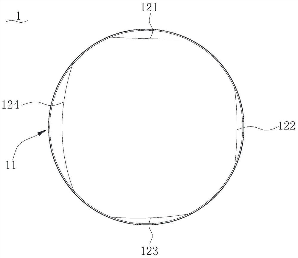
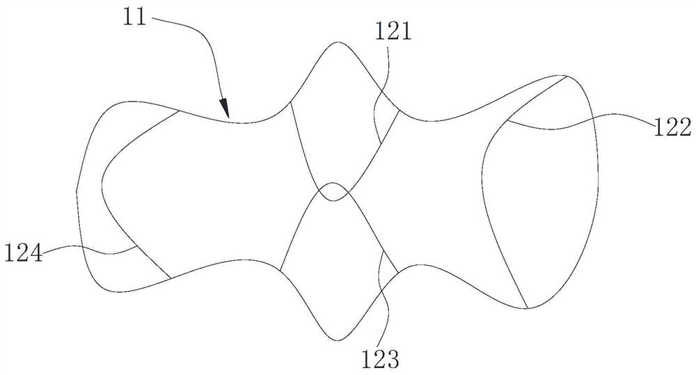
[0091] see Figure 1 to Figure 2 With the structure shown, the stent graft 1 of this embodiment includes a stent graft body 11 and a binding mechanism.
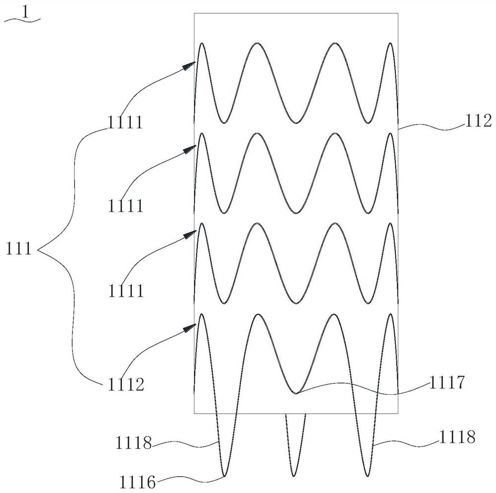
[0092] The stent-graft body 11 includes a stent 111 and a membrane 112 disposed on the surface of the stent 111 .
[0093] The bracket 111 includes a plurality of support rings, and the plurality of support rings are arranged along the axial direction and make the whole cylindrical shape.
[0094] Each support ring is ring-shaped, and a complete circle is arranged along the circumferential direction. Each support ring can shrink or expand in the radial direction, thereby enabling the stent 111 to shrink or expand in the radial direction.
[0095] Specifically, each support ring includes a plurality of support rods connected in sequence at an angle. In the present application, "connected at an angle" refers to being connected to each other and forming an included angle greater than 0 degrees and less than 180 degrees. A pl...
no. 3 example
[0150] refer to Figure 14 , Figure 15 with Figure 16 The difference between this embodiment and the first embodiment of the stent-graft is that the binding mechanism in this embodiment is located on the outer periphery of the stent-graft body 31 .
[0151] The binding mechanism also includes a plurality of wire harness assemblies 32 arranged at intervals along the stent graft body 31 .
[0152] Both ends of each wire harness assembly 32 are fixedly connected to the outer periphery of the stent graft body 31 . Specifically, in this embodiment, the two ends of the wire harness assembly 32 are arranged at intervals along the axial direction of the stent-graft body 31 , and the connecting line between the two ends is parallel to the axis of the stent-graft body 31 .
[0153] Specifically, the wire harness assembly 32 is made of nickel-titanium wire.
[0154] The contraction principle of the wire harness assembly 32 is as follows:
[0155] refer to Figure 17 , when the wi...
no. 4 example
[0165] The difference between this embodiment and the second embodiment of the stent-graft is that: the two ends of the wire harness assembly are arranged at intervals along the circumferential direction of the stent-graft body, and the two ends are located at the same axial height.
[0166] Define the ends of the harness assembly as the first end and the second end.
[0167] The retraction principle of the harness assembly is as follows:
[0168] When the wire harness assembly is shrinking, the middle area starts from the first end, winds along the direction from the first end to the second end and returns to the first end, and at the first end, the direction of the wire harness assembly from the proximal end to the distal end Pass through the wire hole and extend distally.
PUM
Abstract
The invention provides a covered stent, a conveying system and a conveying method. The covered stent comprises a covered stent body and a binding mechanism. The covered stent body is cylindrical; the binding mechanism comprises a plurality of wire harness assemblies which are arranged at intervals in the axial direction of the covered stent body; each wire harness assembly can extend in the axial direction of the covered stent body to provide a connecting hole; any two adjacent wire harness assemblies comprise the first wire harness assembly and the second wire harness assembly, the first wire harness assembly extends to the second wire harness assembly in the axial direction of the covered stent body, and the second wire harness assembly penetrates through a connecting hole of the first wire harness assembly to achieve connection; the multiple wire harness assemblies extend in the same direction, and in the extending direction from the first wire harness assembly to the second wire harness assembly, the connecting hole of the wire harness assembly located at the tail end allows a traction guide wire to penetrate through; and when the multiple wire harness assemblies are sequentially connected in the axial direction of the covered stent body, all the wire harness assemblies shrink in the radial direction of the covered stent body, so that the covered stent body shrinks in the radial direction.
Description
technical field [0001] The invention relates to the technical field of medical devices, in particular to a covered stent, a delivery system and a delivery method. Background technique [0002] Cardiovascular and peripheral vascular diseases seriously affect human health and even endanger life. The most advanced and ideal treatment method at this stage is interventional therapy. Interventional therapy is an emerging subject that uses minimally invasive methods and integrates medical imaging and clinical medicine to achieve therapeutic effects. It has small trauma to patients, high safety and high effectiveness. [0003] For the interventional treatment of cardiovascular and cerebrovascular diseases and peripheral vascular diseases, stents are often used. The stents are delivered to the lesion position through small wounds or natural orifices of the human body and then adjusted and released. Among them, some covered stents need to be applied to the stent-binding process in th...
Claims
Application Information
Patent Timeline
Application Date:The date an application was filed.
Publication Date:The date a patent or application was officially published.
First Publication Date:The earliest publication date of a patent with the same application number.
Issue Date:Publication date of the patent grant document.
PCT Entry Date:The Entry date of PCT National Phase.
Estimated Expiry Date:The statutory expiry date of a patent right according to the Patent Law, and it is the longest term of protection that the patent right can achieve without the termination of the patent right due to other reasons(Term extension factor has been taken into account ).
Invalid Date:Actual expiry date is based on effective date or publication date of legal transaction data of invalid patent.