Optical sheet manufacturing device and manufacturing method

Inactive Publication Date: 2017-09-07
NIPPON CARBIDE KOGYO KK
View PDF0 Cites 1 Cited by
  • Summary
  • Abstract
  • Description
  • Claims
  • Application Information

AI Technical Summary

Benefits of technology

[0034]In the case of providing this configuration, in the first belt and the second belt, the height difference of the irregularities of the first belt, from which the forming resin is released, is small. Thus, the forming resin can be easily released from the surface of the first belt, compared with the case in which the height differen

Problems solved by technology

In such optical sheets, the accuracy of the shape of the optica

Method used


Image

  • Optical sheet manufacturing device and manufacturing method
  • Optical sheet manufacturing device and manufacturing method
  • Optical sheet manufacturing device and manufacturing method

Examples


first embodiment

(1) First Embodiment

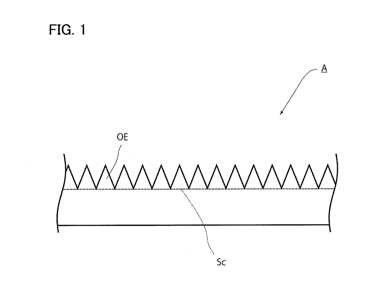
[0044]FIG. 1 is a cross-sectional view of an exemplary optical sheet according to a first embodiment. As illustrated in FIG. 1, an optical sheet A according to the embodiment is formed of a transparent resin. A large number of optical elements OE are formed on one surface. The optical element OE is a columnar triangular prism. In the case of the embodiment, the columnar triangular prisms are disposed on a common plane Sc.

[0045]The optical element OE described above has properties that condense light entered from one of the surfaces of the optical sheet A, which is the surface located on the opposite side of the optical elements OE, on the outer side of the optical elements OE, and then emit the light. Note that, the height of the optical element OE (the height from the common plane Sc) is not limited specifically. However, in order to obtain excellent optical properties, the height is preferably in a range of 0.5 to 200 μm, and more preferably in a range of 7 to ...

second embodiment

(2) Second Embodiment

[0115]Next, a second embodiment will be described in detail. However, components the same as or equivalent to the components of the first embodiment are designated the same reference numerals and signs, and the overlapping description is appropriately omitted.

[0116]FIG. 5 is a cross-sectional view of an exemplary optical sheet according to the second embodiment. As illustrated in FIG. 5, an optical sheet E according to the embodiment is configured of a first optical layer B, a second optical layer C, and a third optical layer D in turn stacked.

[0117]A large number of optical elements OE1 are formed on the surface of the first optical layer B on the opposite side of the face opposed to the second optical layer C. A large number of optical elements OE2 are formed on the surface of the third optical layer D on the opposite side of the face opposed to the second optical layer C. Note that, the shapes and sizes of the optical element OE1 and OE2 may be the same or di...


PUM

PropertyMeasurementUnit
Heightaaaaaaaaaa
Surface temperatureaaaaaaaaaa

Abstract

A manufacturing device for an optical sheet according to the present invention includes a first belt 34 extending on a first heating roll 31 and a first chill roll 32 and a second belt 44 extending on a second heating roll 41 and a second chill roll 42. The first heating roll 31 presses, from the surface of the second belt 44, a second belt non-contact portion PT2 of the second belt 44 facing the first belt 34 where the second heating roll 41 is not in contact with the second chill roll 42. The second chill roll 42 presses, from the surface of the first belt, a first belt non-contact portion PT1 of the first belt 34 facing the second belt 44 where the first heating roll 31 is not in contact with the first chill roll 32.

Description

TECHNICAL FIELD[0001]The present invention relates to a manufacturing device and a manufacturing method for an optical sheet, which are suitable for the case of manufacturing an optical sheet whose parameters are much closer to design values.BACKGROUND ART[0002]Heretofore, as sheets having various optical functions, optical sheets are used, in which an aggregate of micro optical elements is formed on the surface of a resin sheet. In such optical sheets, the accuracy of the shape of the optical elements greatly affects the performance of the optical sheet. Thus, it is requested to manufacture an optical sheet with parameters much closer to design values.[0003]As a manufacturing method for an optical sheet, Patent Literature 1 below is disclosed. In the manufacturing method of Patent Literature 1 below, an emboss belt (20) looped around drive rolls (21 and 22) is opposed to a pressure belt (30) looped around drive rolls (31 and 33), and a thermoplastic resin sheet (60) is supplied bet...

Claims


Application Information

Patent Timeline
IPC IPC(8): B29C59/04B29C43/52G02B5/02B29C48/08B29C48/91
CPCB29C59/046G02B5/0215B29C43/52G02B5/02B29C59/02B29C2043/527B29K2995/0018B29K2995/003B29C2043/522B29C59/04G02B5/045B29C48/08B29C48/91B29C48/914B29C48/918B29C48/9185
Inventor MIMURA, IKUOHAYASHI, CHIHIRO
Owner NIPPON CARBIDE KOGYO KK
Why Eureka
Try Eureka