Gantry type hydraulic correction device

A calibration device, gantry-type technology, applied in the direction of forming tools, manufacturing tools, metal processing equipment, etc., can solve the problems of inconvenient calibration, low work efficiency, insufficient calibration accuracy, etc., to achieve convenient use, improve calibration accuracy, and improve calibration speed Effect

Pending Publication Date: 2021-08-20
张林
View PDF0 Cites 0 Cited by
  • Summary
  • Abstract
  • Description
  • Claims
  • Application Information

AI Technical Summary

Problems solved by technology

[0005] The purpose of the present invention is: in order to solve the problem that the existing gantry-type hydraulic correction device can only move left and right during the process of correcting the vehicle during use, and the hydraulic cylinder for horizontal correction cannot rotate and cannot be lifted at the same time, which is not only inconvenient Correction, in the process of correcting different parts of the vehicle, and the position of the vehicle needs to be constantly moved, which will not only cause insufficient correction accuracy, but also lead to low work efficiency. The invention provides a gantry type hydraulic correction device

Method used


Image

  • Gantry type hydraulic correction device
  • Gantry type hydraulic correction device
  • Gantry type hydraulic correction device

Examples


Embodiment 1

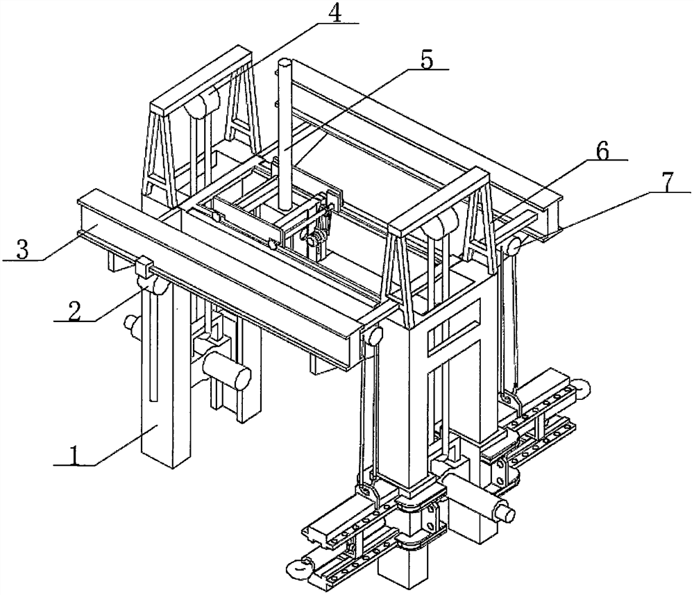
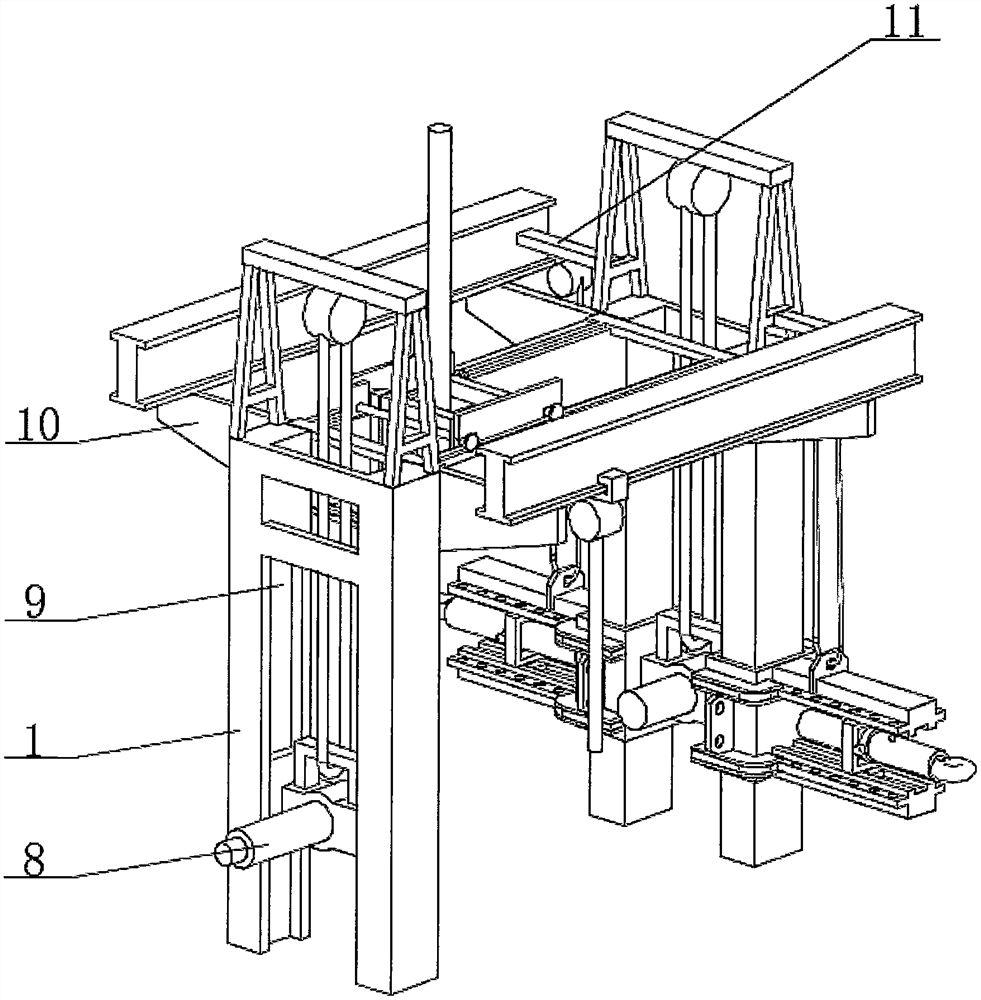
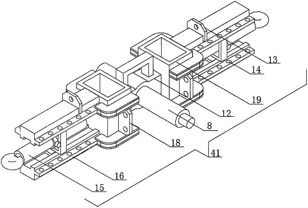
[0028] see Figure 1-8 , a gantry type hydraulic correction device, comprising double columns 1 arranged in parallel, the corresponding inner top of the double columns 1 is fixedly connected with a crossbeam 26, the top of the crossbeam 26 is provided with an upper beam frame 31 in parallel, and the two ends of the upper beam frame 31 All are fixedly connected with the lower beam frame 43 that the top is close to the bottom surface of the cross beam 26 by the fixed frame 35 in parallel, the two ends of the upper beam frame 31 are all fixedly connected with the mounting plate 17 perpendicular to the upper beam frame 31, and the top of the lower beam frame 43 Mounting frame 33 is provided, and the center of mounting frame 33 is fixedly connected with the vertical hydraulic cylinder 5 that runs through mounting frame 33 up and down. The top is all parallel to be provided with slide rail 25, and one end bottom of fixed plate 37 and mounting plate 17 is all rotatably connected with...


PUM


Abstract

The invention discloses a gantry type hydraulic correction device, and relates to the technical field of vehicle correction. The gantry type hydraulic correction device comprises double stand columns arranged in parallel, wherein the tops of the corresponding inner sides of the double stand columns are fixedly connected with a cross beam, the top of the cross beam is provided with an upper beam frame in parallel, the two ends of the upper beam frame are fixedly connected with lower beam frames in parallel through fixing frames, the tops of the lower beam frames are tightly attached to the bottom face of the cross beam, the two ends of the upper beam frame are fixedly connected with mounting plates perpendicular to the upper beam frame, mounting frames are arranged on the tops of the lower beam frames, a vertical hydraulic cylinder penetrating through the upper face and the lower face of the mounting frame is fixedly connected to the center of the mounting frame, and fixing plates are fixedly connected to the two sides of the mounting frame. According to the correction device, the driving mechanism is arranged on one side of the upper beam frame, one side of each lower beam frames and one side of the mounting frame, in the process that the device is used for correcting a vehicle, four-direction movement can be conducted, the situation that the vehicle needs to be continuously moved when different parts of the vehicle are corrected is avoided, and the vehicle correction speed is increased.

Description

technical field [0001] The invention relates to the technical field of vehicle correction, and more specifically relates to a gantry type hydraulic correction device. Background technique [0002] In the event of a vehicle accident, after a severe impact, the outer covering parts of the body and the steel plates of the structural parts will be deformed. The damage to these covering parts can be repaired with various body repair tools, but the damage to the structural parts of the body cannot be done with these tools alone. Repaired, at this time, a body calibration instrument is needed for calibration. If only the body is repaired without body calibration, various faults will occur in the vehicle, such as vehicle deviation, abnormal tire wear, abnormal noise of the vehicle body, etc. , The quality of the body calibration work directly affects the safety of the car, the time used for repair and the repair quality of the whole car. The existing gantry-type hydraulic correctio...

Claims


Application Information

Patent Timeline
Patent Type & Authority Applications(China)
IPC IPC(8): B21D1/12B21D37/04
CPCB21D1/12B21D37/04
Inventor 张林
Owner 张林
Why Eureka
Try Eureka