Welding method for type-c tinplate joint and shell

A welding method and tinplate technology, applied in welding equipment, laser welding equipment, metal processing equipment, etc., can solve the problems of easy breakdown and weak welding at the welding place, and achieve the effect of avoiding too dense solder joints

Pending Publication Date: 2021-08-20
深圳市艾雷激光科技有限公司
View PDF7 Cites 0 Cited by
  • Summary
  • Abstract
  • Description
  • Claims
  • Application Information

AI Technical Summary

Problems solved by technology

[0004] The main purpose of the present invention is to provide a welding method between the type-c tinplate joint and the shell, aiming at solving the technical problem in the prior art that the middle position of the tinplate joint and the shell weld are prone to breakdown or welding is not firm

Method used


Image

  • Welding method for type-c tinplate joint and shell
  • Welding method for type-c tinplate joint and shell

Examples


Embodiment Construction

[0032] The following will clearly and completely describe the technical solutions in the embodiments of the present invention with reference to the accompanying drawings in the embodiments of the present invention. Obviously, the described embodiments are only part of the embodiments of the present invention, not all of them. Based on the embodiments of the present invention, all other embodiments obtained by persons of ordinary skill in the art without creative efforts fall within the protection scope of the present invention.

[0033] It should be noted that all directional indications (such as up, down, left, right, front, back...) in the embodiments of the present invention are only used to explain the relationship between the components in a certain posture (as shown in the accompanying drawings). Relative positional relationship, movement conditions, etc., if the specific posture changes, the directional indication will also change accordingly.

[0034] In the present in...


PUM


Abstract

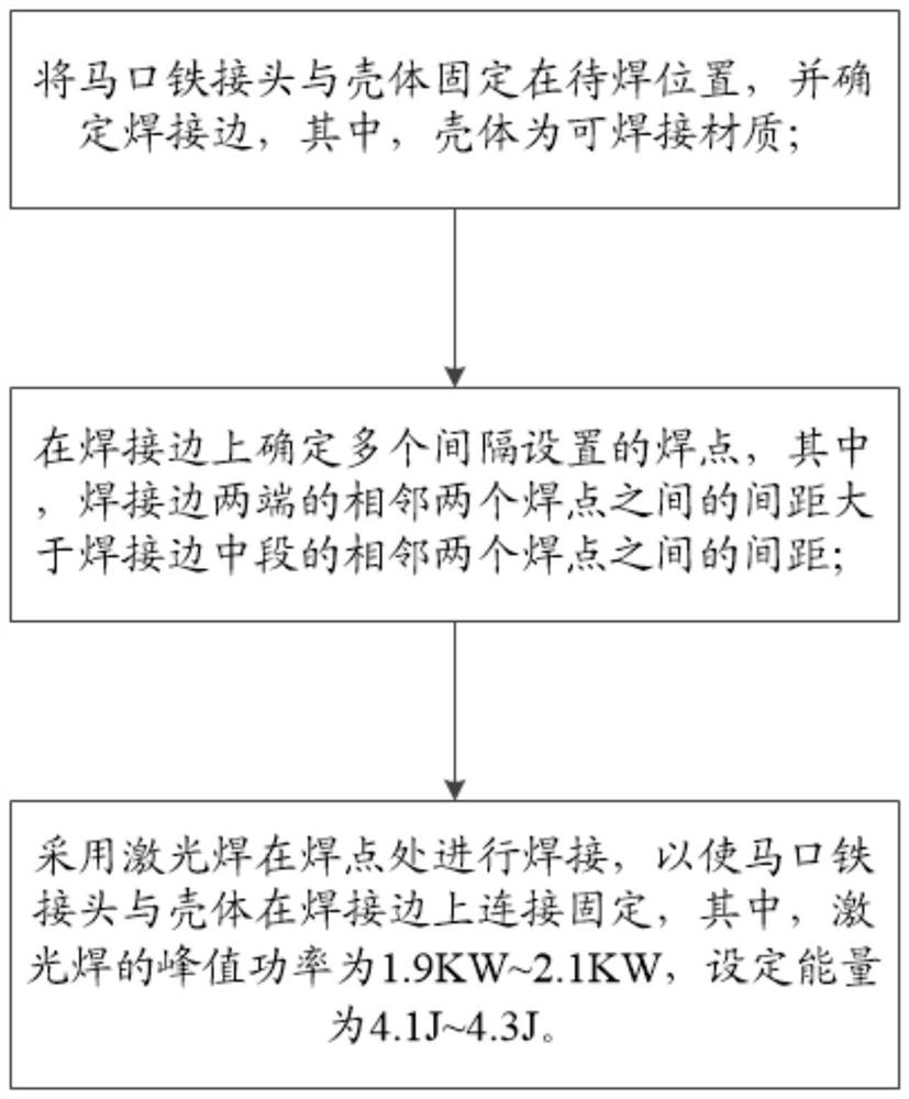
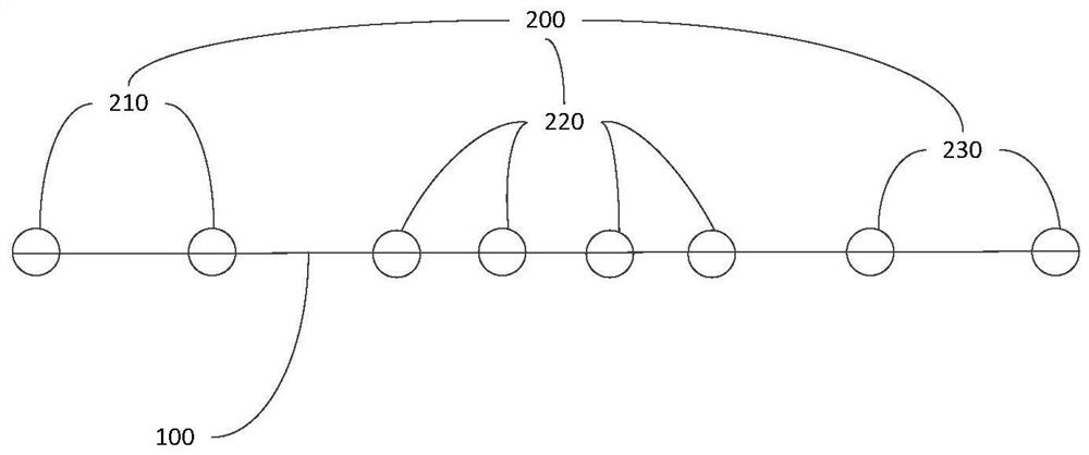
The invention relates to a manufacturing technology of a type-c tinplate joint, and discloses a welding method of the type-c tinplate joint and a shell. The welding method of the type-c tinplate joint and the shell comprises the following steps that the tinplate joint and the shell are fixed to a to-be-welded position, and a welding edge is determined; a plurality of welding spots arranged at intervals are determined on the welding edge, and the distance between every two adjacent welding spots at the two ends of the welding edge is larger than that between every two adjacent welding spots in the middle section of the welding edge; laser welding is adopted for welding at the welding spots, so that the tinplate joint and the shell are connected and fixed on the welding edge, the peak power of laser welding is 1.9 KW-2.1 KW, and the set energy is 4.1J-4.3J. According to the welding method for the type-c tinplate joint and the shell, the tensile force generated after the tinplate joint and the shell are welded can be guaranteed, and meanwhile the phenomenon of breakdown during welding can be avoided.

Description

technical field [0001] The invention relates to the technical field of assembly of type-c tinplate joints, in particular to a welding method between a type-c tinplate joint and a casing. Background technique [0002] The type-c tinplate joint is often formed by connecting the shell and the tinplate joint. The tinplate joint is assembled in the installation port of the shell. The gap between the middle position of the tinplate joint in the installation port and the shell is relatively large. In the existing laser welding technology, The solder joints on the welding edge are mostly distributed at equal intervals. When using this laser welding method to weld the tinplate joint and the shell, the middle position of the tinplate joint and the weld of the shell are prone to breakdown or poor welding. [0003] The above content is only used to assist in understanding the technical solution of the present invention, and does not mean that the above content is admitted as prior art. ...

Claims


Application Information

Patent Timeline
Patent Type & Authority Applications(China)
IPC IPC(8): B23K26/06B23K26/22B23K26/70
CPCB23K26/0626B23K26/22B23K26/702
Inventor 蒋丽君刘坤
Owner 深圳市艾雷激光科技有限公司
Why Eureka
Try Eureka