Eureka AIR delivers breakthrough ideas for toughest innovation challenges, trusted by R&D personnel around the world.

Test system for fatigue life of cooling channels

A technology of cooling channels and fatigue life, applied in the field of aerospace universities, can solve the problems of inability to judge the fatigue life of cooling channels, coolant leakage, etc.

Active Publication Date: 2022-07-01
BEIHANG UNIV
View PDF0 Cites 0 Cited by
  • Summary
  • Abstract
  • Description
  • Claims
  • Application Information

AI Technical Summary

Problems solved by technology

[0005] The purpose of this application is to provide a test system for the fatigue life of the cooling channel to solve the problem that the fatigue life of the cooling channel cannot be judged in the prior art to a certain extent, which eventually leads to the direct leakage of the coolant into the high-temperature gas, causing Technical issues with catastrophic consequences

Method used


Image

  • Test system for fatigue life of cooling channels
  • Test system for fatigue life of cooling channels
  • Test system for fatigue life of cooling channels

Examples


Embodiment 1

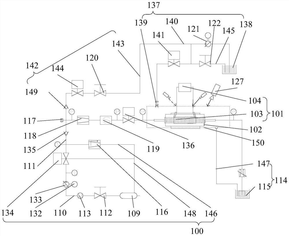
[0058] combine figure 1 As shown, a testing system for fatigue life of cooling channels includes: a coolant supply unit 100 and a heating unit 101; the coolant supply unit 100 is used for supplying coolant to the cooling channel 102; the heating unit 101 heating the cooling channel 102 with a preset heating temperature, a preset heating time and a preset number of times of heating;

[0059] Specifically, first, the heating unit 101 is used to perform a single time on the cooling channel 102 with a preset heating time, wherein the heating efficiency of the heating unit 101 simulates the actual ignition of the liquid rocket engine; then the cooling channel 102 is heated with a preset number of heating times, Heating is stopped until cracks appear in the cooling channel 102 ; finally, the fatigue life of the cooling channel 102 can be calculated according to the preset heating temperature, the preset heating time and the preset heating times of the heating unit 101 .

[0060] In...

Embodiment 2

[0102] The testing system for fatigue life of cooling channels in the second embodiment is an improvement on the basis of the above-mentioned embodiment. The technical content disclosed in the above-mentioned embodiment is not described repeatedly, and the content disclosed in the above-mentioned embodiment also belongs to this embodiment. 2. The contents of the disclosure.

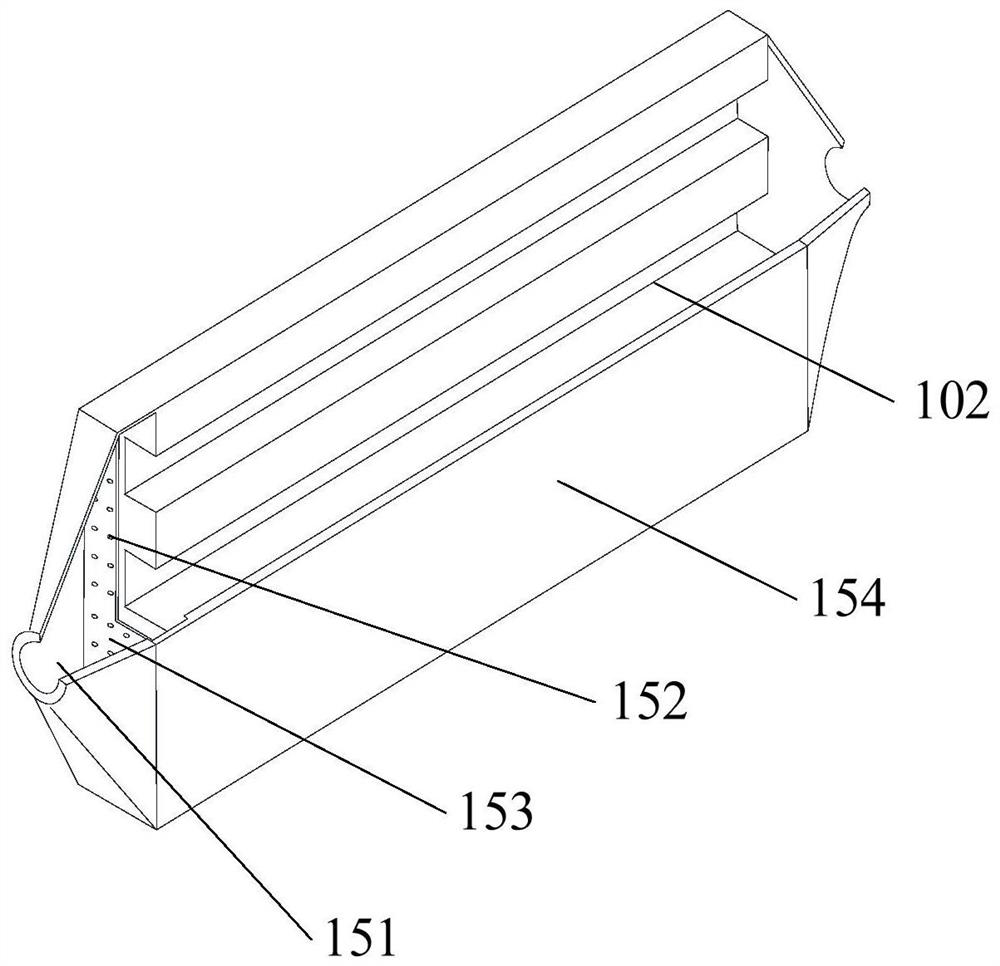
[0103] In this embodiment, the heating unit 101 includes an induction coil 103, a power source 104 and a magnetic component; the induction coil 103 is connected to the power source 104; the induction coil 103 has an accommodating space, and the test panel is arranged in the accommodating space In the space, one end face of the test panel is the test face 154, the test face 154 is the heated face, the end face opposite to the test face 154 is provided with a magnetic element, and the test face 154 is the non-heated face.

Embodiment 3

[0105] The testing system for fatigue life of cooling channels in the third embodiment is an improvement on the basis of the above-mentioned embodiments, the technical contents disclosed in the above-mentioned embodiments are not described repeatedly, and the contents disclosed in the above-mentioned embodiments also belong to this embodiment. Three disclosed contents.

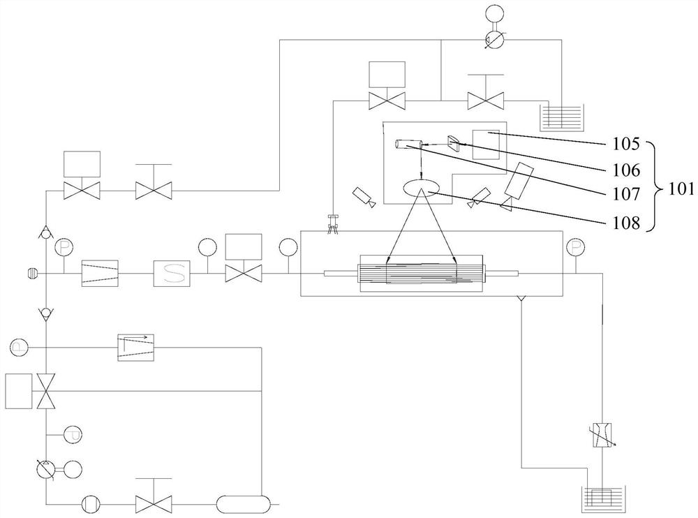
[0106] combine image 3 As shown, in this embodiment, the cooling channel 102 is heated by means of laser heating. Specifically, laser heating is to use laser energy to heat the cooling channel 102, so that the laser beam is radiated on the side of the cooling channel 102 to be heated. , The laser power in the radiation area is high, and the heating speed is fast, the efficiency is high, the beam adjustment is convenient, and it is easier to digitally control and automate operations.

[0107] Specifically, the heating unit 101 includes a laser source 105, a scanning galvanometer 107, a shaping mirror 106 and ...


PUM


Abstract

The present application relates to the technical field of University of Aeronautics and Astronautics, and in particular to a testing system for fatigue life of cooling channels, which includes: a coolant supply unit and a heating unit; the coolant supply unit is used for supplying coolant to the cooling channels; heating The unit heats the cooling channel with a preset heating temperature, a preset heating time, and a preset number of heating times; specifically, firstly, the cooling channel is heated for a single time by the heating unit with a preset heating time, wherein the heating efficiency of the heating unit simulates a liquid rocket The actual ignition situation of the engine; then, the cooling channel is heated with a preset number of heating times, and the heating is stopped until cracks appear in the cooling channel; finally, according to the preset heating temperature, preset heating time and preset heating times of the heating unit can The fatigue life of the cooling channel is calculated.

Description

technical field [0001] The present application relates to the technical field of the University of Aeronautics and Astronautics, in particular to a testing system for fatigue life of cooling channels. Background technique [0002] The combustion chamber of the liquid rocket engine has high thermal strength, and the gas has the characteristics of high temperature, high pressure and high speed. The gas and the wall of the combustion chamber will undergo violent convection and radiation heat exchange. The cooling of the cooling channel is carried out by the coolant flowing through the cooling channel; the temperature of the outer wall of the cooling channel is close to the temperature of the coolant, and the temperature of the gas wall is close to 900K. The huge temperature difference between the two causes the inner wall to bear severe thermal load, resulting in The thermal stress usually exceeds the elastic limit of its inner wall material, and the inner wall undergoes plasti...

Claims


Application Information

Patent Timeline
Patent Type & Authority Patents(China)
IPC IPC(8): G01M15/14
CPCG01M15/14
Inventor 田辉李心瞳张源俊魏天放周闯
Owner BEIHANG UNIV
Why Eureka
Eureka Blog
Learn More