Eureka AIR delivers breakthrough ideas for toughest innovation challenges, trusted by R&D personnel around the world.

System for testing fatigue life of cooling channel

A cooling channel and fatigue life technology, applied in the field of aerospace universities, can solve the problems of coolant leakage, inability to judge the fatigue life of cooling channels, etc.

Active Publication Date: 2021-08-27
BEIHANG UNIV
View PDF5 Cites 0 Cited by
  • Summary
  • Abstract
  • Description
  • Claims
  • Application Information

AI Technical Summary

Problems solved by technology

[0005] The purpose of this application is to provide a test system for the fatigue life of the cooling channel to solve the problem that the fatigue life of the cooling channel cannot be judged in the prior art to a certain extent, which eventually leads to the direct leakage of the coolant into the high-temperature gas, causing Technical issues with catastrophic consequences

Method used


Image

  • System for testing fatigue life of cooling channel
  • System for testing fatigue life of cooling channel
  • System for testing fatigue life of cooling channel

Examples


Embodiment 1

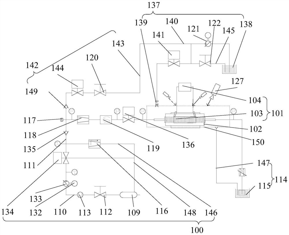
[0058] Combine figure 1 As shown, a test system for the fatigue life of the cooling channel, including: coolant supply unit 100 and a heating unit 101; the coolant supply unit 100 is used to supply a coolant for the cooling passage 102; the heating unit 101 The cooling passage 102 is heated by preset heating temperature, preset heating time, and preset heating.

[0059] Specifically, the cooling passage 102 is first performed by the heating unit 101 by a preset heating time, wherein the heating efficiency of the heating unit 101 simulates the actual ignition of the liquid rocket engine; then heating in the cooling passage 102 in the preset heating. Until the cooling passage 102 cracks, stop heating; finally, the fatigue life of the cooling passage 102 can be calculated according to the preset heating temperature of the heating unit 101, the preset heating time, and the preset heating.

[0060] In this embodiment, the coolant supply unit 100 is used to store the coolant's storage t...

Embodiment 2

[0102] The test system for the fatigue life of the cooling passage in this embodiment is an improvement on the above embodiment. The technical content disclosed in the above embodiment is not repeated, and the content disclosed in the above-described embodiments belongs to this embodiment. Two disclosed content.

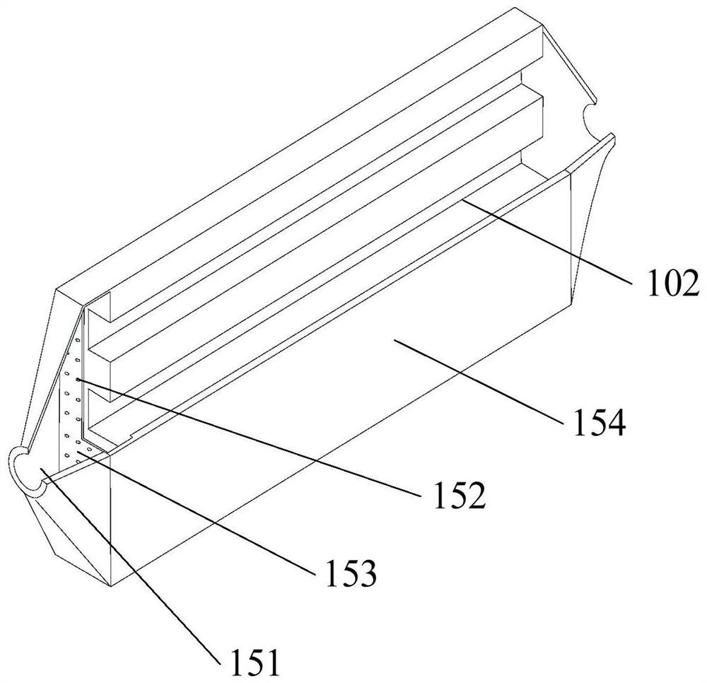
[0103] In this embodiment, the heating unit 101 includes an induction coil 103, a power source 104, and a magnetic member; the induction coil 103 is connected to the power source 104; the induction coil 103 has an accommodating space, the test panel being set to accommodate In the space, the end surface on the test panel is a test surface 154, and the test surface 154 is a heated surface, and a magnetic member is provided with an end face side opposite to the test surface 154, which is a non-heated surface.

Embodiment 3

[0105] The test system for the fatigue life of the cooling channel in this embodiment is an improvement on the above embodiment. The technical content disclosed in the above embodiment is not repeated, and the content disclosed in the above embodiments belongs to this embodiment. Three disclosed content.

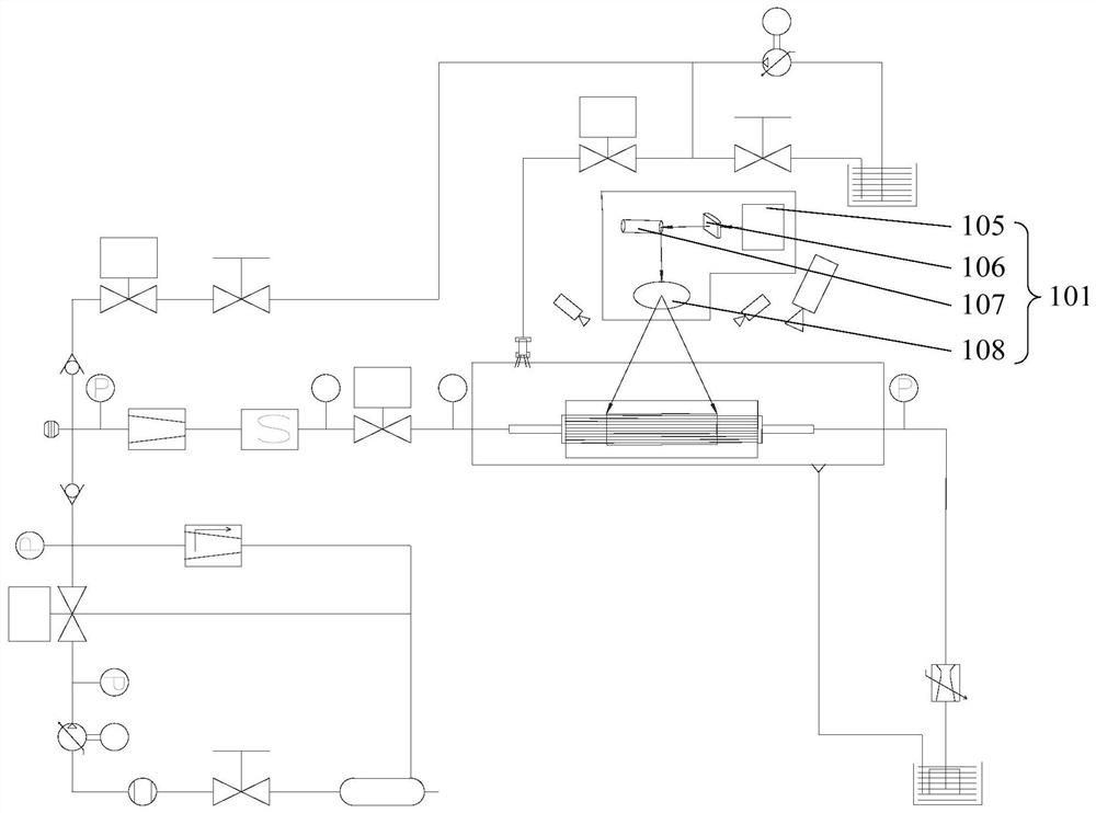
[0106] Combine image 3 As shown in this embodiment, the cooling passage 102 is heated in such a manner that the cooling passage 102 is heated, specifically, the laser heating is heated by the laser energy to heat the cooling passage 102, so that the laser beam is radiated on the heat sides of the cooling passage 102. The laser power in the radiation region is high, and the heating speed is fast, the efficiency is high, and the beam adjustment is convenient, it is easier to digital control and automation.

[0107] Specifically, the heating unit 101 includes a sequentially arranged laser source 105, a scanning gamber 107, a shaped mirror 106, and a focus mirror 108; the focusing m...


PUM


Abstract

The invention relates to the technical field of aerospace universities, in particular to a system for testing the fatigue life of a cooling channel, which comprises a coolant supply unit and a heating unit. The coolant supply unit is used for supplying coolant to the cooling channel. The heating unit heats the cooling channel at a preset heating temperature, preset heating time and a preset heating frequency. Specifically, the heating unit heats the cooling channel for a single time at preset heating time, and the heating efficiency of the heating unit simulates the actual ignition condition of a liquid-propellant rocket engine; the cooling channel is heated according to the preset heating frequency, and heating is stopped when the cooling channel has cracks; and finally, the fatigue life of the cooling channel is calculated according to the preset heating temperature, the preset heating time and the preset heating frequency of the heating unit.

Description

Technical field [0001] The present application relates to the technical field of aerospace, in particular, involving a test system for the fatigue life of the cooling channel. Background technique [0002] The combustion chamber of the liquid rocket engine has a high thermal intensity, the gas has a high temperature, high pressure, and high speed, etc., and the wall surface of the gas and the combustion chamber will have severe convection and radiation heat exchange, and the existing outer cooling method is realized to the combustion chamber. The cooling is cooled, which is cooled by a coolant flowing through the cooling passage; wherein the temperature of the cooling passage is close to the temperature of the coolant. The gas wall temperature is close to 900K, and the large temperature difference causes the inner wall to withstand severe thermal load, thereby producing The thermal stress is usually more than the elastic limit of its inner wall material, and plastic deformation o...

Claims


Application Information

Patent Timeline
Patent Type & Authority Applications(China)
IPC IPC(8): G01M15/14
CPCG01M15/14
Inventor 田辉李心瞳张源俊魏天放周闯
Owner BEIHANG UNIV
Why Eureka
Eureka Blog
Learn More