Air film cooling composite hole structure for turbine blade and turbine blade

A technology of turbine blade and air film cooling, which is applied in the direction of supporting elements of blades, machines/engines, mechanical equipment, etc., can solve the problem of low diffusion capacity of air film jet flow in the span direction, achieve excellent cooling effect, improve cooling effect, and enhance The effect of lateral spreading ability

Active Publication Date: 2021-09-07
XI AN JIAOTONG UNIV
View PDF7 Cites 2 Cited by
  • Summary
  • Abstract
  • Description
  • Claims
  • Application Information

AI Technical Summary

Problems solved by technology

[0004] In order to overcome the defects in the above-mentioned prior art, the object of the present invention is to provide a film cooling compound hole structure and a turbine blade for a turbine blade, which solves the problem that the spanwise diffusion ability of the film jet of the horizontal groove film hole is relatively large. low problem

Method used


Image

  • Air film cooling composite hole structure for turbine blade and turbine blade
  • Air film cooling composite hole structure for turbine blade and turbine blade
  • Air film cooling composite hole structure for turbine blade and turbine blade

Examples


Embodiment 1

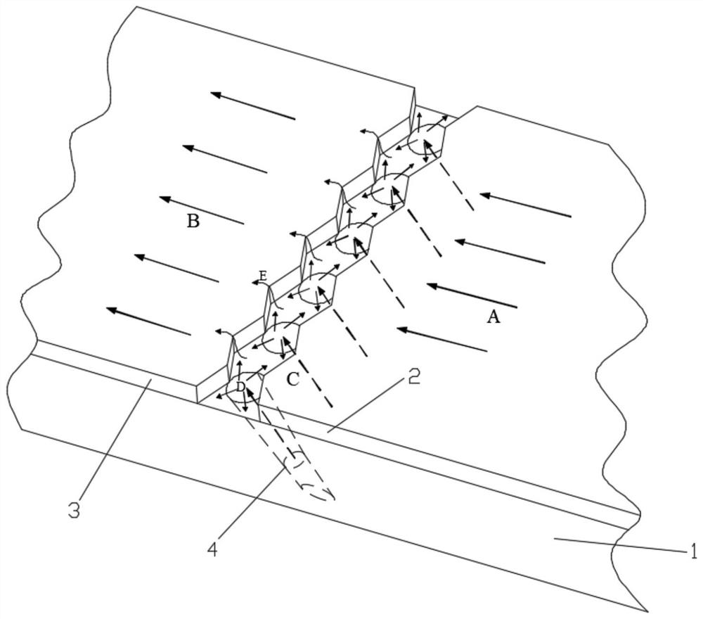
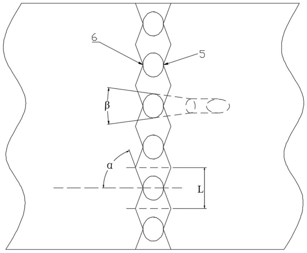
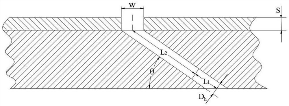
[0041] The dumbbell-shaped groove film cooling compound hole structure of the turbine blade in this embodiment, such as Figure 5 As shown, the pressure surface of the turbine blade is processed with a dumbbell-shaped groove air film hole 10 on the pressure surface, and the suction surface is processed with a dumbbell-shaped groove air film hole 11 on the suction surface, and the air is supplied by the internal cooling channel 12; A dumbbell-shaped groove is provided at the outlet of the composite gas film hole 4 . Wherein the structure of the compound air film hole 4 is composed of a spanwise expansion section 8 and a straight hole section 9, and the diameter of the straight hole section 9 is D h The value is 1mm, and the length of the straight hole section 9 is L 1 2mm, length L of spanwise expansion section 8 2 The size is 6mm, the spanwise expansion angle β is 10°, and the gas film hole flow direction inclination angle θ is 35°. The angle α between the side of the dumbb...

Embodiment 2

[0044] The air film hole 10 is processed on the pressure surface with a dumbbell-shaped groove on the pressure surface, and the air film hole 11 is processed on the suction surface with a dumbbell-shaped groove on the suction surface, and the air is supplied by the internal cooling channel 12; There are dumbbell-shaped grooves in the part. Wherein the structure of the compound air film hole 4 is composed of a spanwise expansion section 8 and a straight hole section 9, and the diameter of the straight hole section 9 is D h The value is 0.5mm, and the length of the straight hole section 9 is L 1 2.99mm, spanwise expansion section 8 length L 2 The size is 3mm, the spanwise expansion angle β is 15°, and the gas film hole flow direction inclination angle θ is 50°. The angle α between the side of the dumbbell-shaped groove and the flow direction of the mainstream gas A is 80°, the throat of the groove is flush with the front and rear edges of the outlet of the composite gas film h...


PUM


Abstract

The invention belongs to the technical field of heat transfer and cooling of hot end components of gas turbines, and relates to an air film cooling composite hole structure for a turbine blade. The turbine blade comprises an air film hole plate and a thermal barrier coating arranged on the air film hole plate, a plurality of composite air film holes are formed in the air film hole plate, and a dumbbell-shaped groove is formed in the thermal barrier coating; and each composite air film hole comprises a spanwise expansion section and a straight hole section which communicate with each other, the straight hole sections communicate with an inner cooling channel of the turbine blade, and outlets of the spanwise expansion sections communicate with the dumbbell-shaped groove. The guiding effect of the dumbbell-shaped groove enables cooling air flow to be diffused in the groove in the transverse direction and the longitudinal direction, the jet flow momentum is weakened, and the spanwise covering capacity is greatly improved. In addition, the dumbbell-shaped groove changes the rotating direction of a kidney-shaped vortex pair, and the vortex pair develops towards the two sides of the groove under the compression action of main flow, so that the cold air jet flow is better attached to the wall surface; and the air film holes comprise the spanwise expansion sections at the outlets, so that the jet flow momentum can be further reduced, the diffusion of an air film in the groove is accelerated, and an excellent cooling effect is achieved.

Description

technical field [0001] The invention belongs to the technical field of heat transfer and cooling of gas turbine hot end components, and relates to a gas film cooling composite hole structure for a turbine blade and the turbine blade. Background technique [0002] With the rapid development of aero-engines, the temperature at the front inlet of the turbine continues to increase, and the temperature at the turbine inlet of advanced engines has reached about 2000K, which has far exceeded the temperature resistance limit of turbine blade materials. In order to ensure the safe operation of the turbine, various cooling technologies are used to cool the blades, mainly including internal cooling and external cooling. External cooling is also called film cooling, that is to extract part of the compressed air from the last stage of the compressor and bypass the combustion chamber directly into the turbine, so that the cooling air is sprayed from the inside of the blade to the side sur...

Claims


Application Information

Patent Timeline
Patent Type & Authority Applications(China)
IPC IPC(8): F01D5/18
CPCF01D5/18F01D5/186Y02T50/60
Inventor 李跃明高俊杨雄伟柴怡君耿谦
Owner XI AN JIAOTONG UNIV
Why Eureka
Try Eureka