Offset hole row and cylindrical hole row combined cooling structure for corrugated heat shield

A corrugated heat shield and cooling structure technology, applied in lighting and heating equipment, combustion methods, combustion chambers, etc., can solve problems such as the existence of optimized space and the configuration of air film holes that are not optimized, and achieve improved cooling efficiency. Cooling effect, effect of improving adhesion

Active Publication Date: 2021-01-05
NORTHWESTERN POLYTECHNICAL UNIV
View PDF8 Cites 0 Cited by
  • Summary
  • Abstract
  • Description
  • Claims
  • Application Information

AI Technical Summary

Problems solved by technology

At present, most of the research is still in the form of uniform and densely distributed holes on the corrugated board. A large amount of cold air fails to exert its due performance. The air film holes on the corrugated surface have not been optimized, and there is room for optimization.

Method used


Image

  • Offset hole row and cylindrical hole row combined cooling structure for corrugated heat shield
  • Offset hole row and cylindrical hole row combined cooling structure for corrugated heat shield
  • Offset hole row and cylindrical hole row combined cooling structure for corrugated heat shield

Examples


Embodiment 1

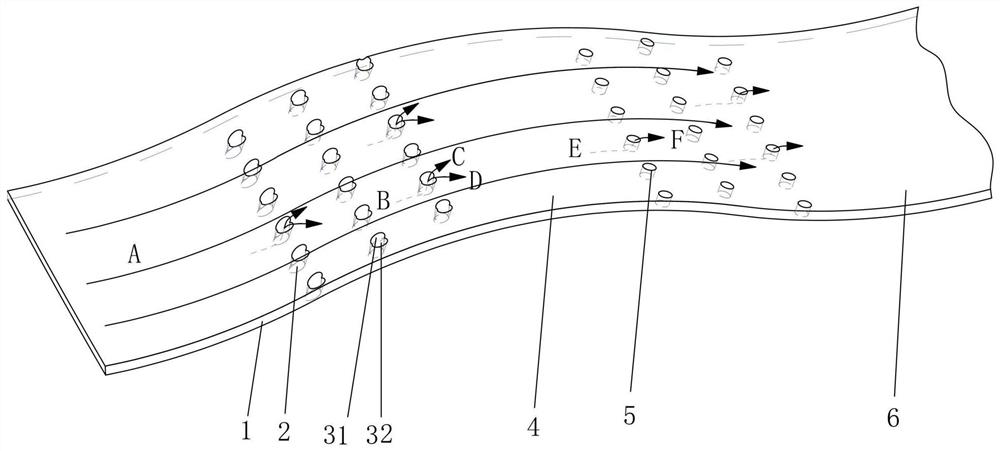
[0040] This embodiment is a combined cooling structure of offset air film hole rows and cylindrical hole rows on the corrugated heat shield. Two rows of offset air film hole rows 2 are arranged on the windward side of the corrugated heat shield, and four rows of cylindrical hole rows 5 are arranged on the leeward surface of the corrugated heat shield. The annular cold air passage surrounded by the heat shield cylinder and the outer combustion chamber cylinder supplies air. The offset air film hole in the offset air film hole row 2 is composed of a cylindrical air film hole and an offset rotating cylindrical hole. The cylindrical air film hole is a circular through hole, and the offset rotating cylindrical hole is The cylindrical air film holes are formed offset around the center of the hole on the side of the cold air channel; the offset air film hole row 2 is concentrated on the second half of the windward side, and there is a small offset distance between adjacent hole rows,...

Embodiment 2

[0045] This embodiment is a combined cooling structure of offset air film hole rows and cylindrical hole rows on the corrugated heat shield. Three rows of offset hole rows 2 are arranged on the windward side of the corrugated heat shield panel 1, and four rows of cylindrical hole rows 5 are arranged on the leeward side of the corrugated heat shield panel 1. Both the offset air film hole row and the cylindrical hole row are made of corrugated The annular cold air passage surrounded by the heat shield plate and the outer combustion chamber cylinder supplies air. The offset air film hole in the offset air film hole row 2 is composed of a cylindrical air film hole and an offset rotating cylindrical hole. The cylindrical air film hole is a circular through hole, and the offset rotating cylindrical hole is The cylindrical air film holes are formed offset around the center of the orifice on the side of the cold air passage; the offset air film hole rows are concentrated in the rear h...

Embodiment 3

[0050] This embodiment is a combined cooling structure of offset air film hole rows and cylindrical hole rows on the corrugated heat shield. Three rows of offset hole rows 2 are arranged on the windward side of the corrugated heat shield panel, and five rows of cylindrical hole rows 5 are arranged on the leeward side of the corrugated heat shield panel. The annular cold air channel surrounded by the cylinder supplies air. The offset air film hole in the offset air film hole row 2 is composed of a cylindrical air film hole and an offset rotating cylindrical hole. The cylindrical air film hole is a circular through hole, and the offset rotating cylindrical hole is The cylindrical air film holes are formed offset around the center of the hole on the side of the cold air channel; the offset air film hole row 2 is concentrated on the second half of the windward side, and there is a small offset distance between adjacent hole rows, and the cylindrical hole row Concentrated in the m...


PUM


Abstract

The invention discloses an offset hole row and cylindrical hole row combined cooling structure for a corrugated heat shield, and belongs to the technical field of cooling of aero-engine combustion chambers. The cooling structure comprises a corrugated heat shield plate, and offset gas film hole rows and cylindrical hole rows which are arranged on the corrugated heat shield plate, wherein the corrugated heat shield plate is of a cylinder structure, a fuel gas channel is formed in the corrugated heat shield plate, an annular channel composed of the cylindrical corrugated heat shield plate and acombustion chamber outer cylinder forms a cold air channel, each corrugation of the corrugated heat shield plate comprises a windward side and a leeward side, 2-3 rows of offset air film hole rows areuniformly distributed on the windward side along the axial direction of the cylindrical corrugated heat shield plate, 3-4 rows of cylindrical hole rows are uniformly distributed on the leeward side along the axial direction of the cylindrical corrugated heat shield plate, the structure is formed by arranging a plurality of offset air film hole rows on the mainstream leeward side of a corrugated plate and arranging a plurality of cylindrical air film hole rows on the windward side, and the structure can be used for a turbofan engine afterburner or a ramjet engine combustor.

Description

technical field [0001] The invention belongs to the technical field of cooling of an aero-engine combustion chamber, and in particular relates to a combined cooling structure of an offset hole row and a cylindrical hole row for a corrugated heat shield. Background technique [0002] In order to meet the needs of short-distance take-off and fast maneuvering, modern military aero-engines are often equipped with afterburners. As the simplest type of air-breathing engine, the ramjet engine has attracted the attention of many countries in the performance research of its combustion chamber due to its simple structure and superiority in the supersonic range. The structures of the above two combustion chambers are similar, but their harsh working conditions have brought challenges to the design research. Specifically, on the one hand, the temperature of the gas in the combustion chamber rises rapidly to 2100K or even higher after ignition, which greatly exceeds the temperature resi...

Claims


Application Information

Patent Timeline
Patent Type & Authority Applications(China)
IPC IPC(8): F23R3/00
CPCF23R3/00F23R3/002F23R2900/03042
Inventor 朱惠人徐志鹏张丽刘存良许卫疆李鑫磊郭涛
Owner NORTHWESTERN POLYTECHNICAL UNIV
Why Eureka
Try Eureka