
Material strip lubricating device

A technology of oiling and stripping materials, which is applied in the direction of surface coating liquid devices, coatings, metal processing equipment, etc., can solve the problems of large oil mist diffusion, impact of stamping, and dross sticking, etc. Achieve the effect of improving the adhesion ability and high uniformity of application

Inactive Publication Date: 2014-12-03
寇兴国 +1
View PDF6 Cites 3 Cited by
  • Summary
  • Abstract
  • Description
  • Claims
  • Application Information

AI Technical Summary

Problems solved by technology

In the prior art, the commonly used oil spraying methods basically include dripping, oiling, and spraying. The advantage of dripping operation is that its pollution is small, and the oil droplets will not drip to the outside of the material belt. Uneven application; during oiling operation, oil the upper and lower sides of the material belt after dipping a felt roller in oil. The material belt sprays oil mist directly, which has the advantage of relatively uniform application, and its disadvantage is that the distance between the nozzle and the material belt is relatively large, and the oil mist spreads greatly during spraying, and the oil mist is not easy to attach to the surface of the material belt.

Method used


Image

  • Material strip lubricating device
  • Material strip lubricating device
  • Material strip lubricating device

Examples


Embodiment Construction

[0015] The specific implementation manner of the present invention will be described below in conjunction with the accompanying drawings.

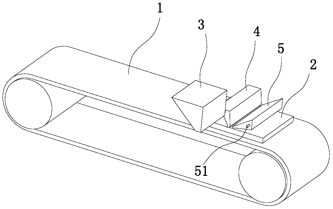
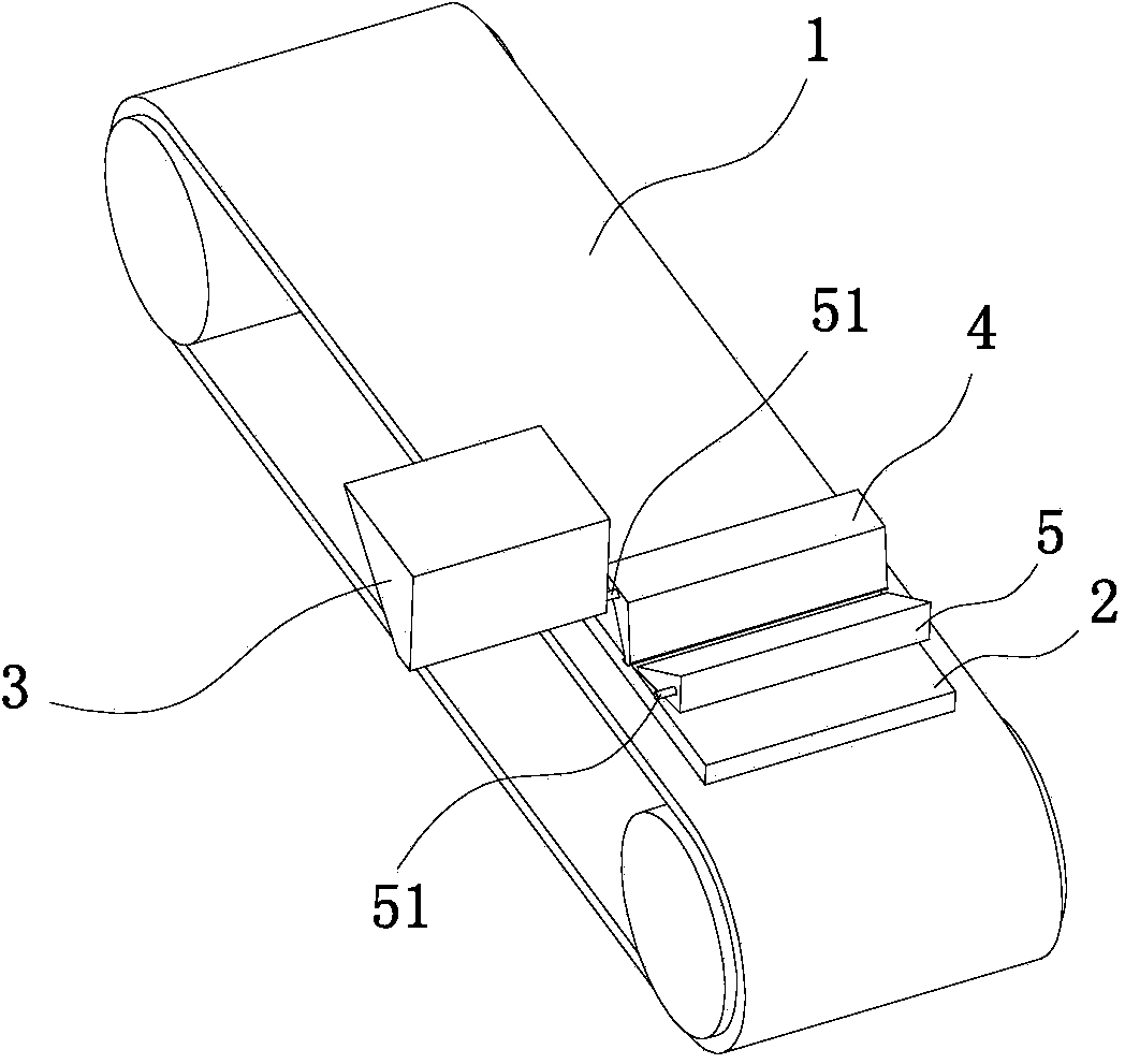
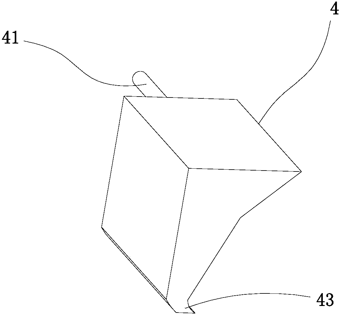
[0016] Such as Figure 1 to Figure 5 As shown, the material belt oiling device of the present embodiment comprises a conveyor belt 1, a material belt 2 is placed on the conveyor belt 1, and an oil drip nozzle 4 is arranged above the material belt 2, and the oil drip nozzle 4 communicates with the fuel tank 3, and the oil drip nozzle 4 is The shell structure has a large upper end and a small lower end. There is an oil pipe 41 connected to the fuel tank 3 on the outer side of the upper end. The oil guide plate 42 is fixedly connected to the inclined inner wall. The high end of the oil guide plate 42 has an arc-shaped oil guide area 421 located on the oil pipe. Below the oil inlet of 41, a plurality of oil leakage holes 422 are evenly distributed on the oil guide plate 42; the lower end of the oil drip nozzle 4 has an oil guide part 43 bent t...


PUM


Abstract

The invention relates to a material strip lubricating device. The material strip lubricating device comprises a conveyor belt; a material strip is placed on the conveyor belt; a dripping nozzle is arranged above the material belt and communicated with an oil tank; the dripping nozzle is of a casing structure with the large upper end and the small lower end; the outer side of the upper end of the dripping nozzle is provided with an oil pipe which is communicated with the oil tank; the inner wall of the dripping nozzle is fixedly connected with an oil guide plate in an inclined mode; the high end of the oil guide plate is provided with an arc-shaped oil guide area and located below an oil inlet of the oil pipe; a plurality of oil leakage holes are uniformly formed in the oil guide plate; the lower end of the dripping nozzle is provided with an oil guide portion with an oil falling groove, wherein the oil guide portion is bent towards the conveying direction of the conveyor belt; the material strip lubricating device also comprises a blow head which is arranged above the material belt and located on the front side of the dripping nozzle; an air nozzle of the blow head is towards the oil falling groove of the dripping nozzle. According to the material strip lubricating device, the oil flow is uniformly guided to drip to the oil guide portion through the oil guide plate, oil droplets are uniformly daubed on the material belt through the oil falling groove due to the oil guide portion, and accordingly the daub uniformity is high and an auxiliary oil layer is attached to the upper surface of the material belt due to the blowing effect of the blow head which is arranged on the front side and accordingly the attachment capability is improved.

Description

technical field [0001] The invention relates to the technical field of stamping equipment, in particular to oiling equipment for stamping strips. Background technique [0002] At present, when producing stamped products, it is necessary to spray stamping oil on the strip to facilitate stamping. In the prior art, the commonly used oil spraying methods basically include dripping, oiling, and spraying. The advantage of dripping operation is that its pollution is small, and the oil droplets will not drip to the outside of the material belt. Uneven application; during oiling operation, oil the upper and lower sides of the material belt after dipping a felt roller in oil. The material belt sprays the oil mist directly, which has the advantage of relatively uniform application, but the disadvantage is that the distance between the nozzle and the material belt is relatively large, and the oil mist spreads greatly during spraying, and the oil mist is not easy to adhere to the surfac...

Claims


Application Information

Patent Timeline
Patent Type & Authority Applications(China)
IPC IPC(8): B21D37/18B05C1/04
Inventor 孙毅刚
Owner 寇兴国
Learn More