Oil nozzle structure with oil coating

A technology of oiling and oiling nozzles on the material belt, which is applied to the surface coating liquid device, coating, spraying device, etc., which can solve the problems of stamping, large oil mist diffusion, and dander sticking, etc., to avoid Pollution, effect of high uniformity of application

Inactive Publication Date: 2016-04-13
张学义 +1
View PDF8 Cites 0 Cited by
  • Summary
  • Abstract
  • Description
  • Claims
  • Application Information

AI Technical Summary

Problems solved by technology

In the prior art, the commonly used oil spraying methods basically include dripping, oiling, and spraying. The advantage of dripping operation is that its pollution is small, and the oil droplets will not drip to the outside of the material belt. Uneven application; during oiling operation, oil the upper and lower sides of the material belt after dipping a felt roller in oil. The material belt sprays oil mist directly, which has the advantage of relatively uniform application, and its disadvantage is that the distance between the nozzle and the material belt is relatively large, and the oil mist spreads greatly during spraying, and the oil mist is not easy to attach to the surface of the material belt.

Method used


Image

  • Oil nozzle structure with oil coating
  • Oil nozzle structure with oil coating

Examples


Embodiment Construction

[0012] The specific implementation manner of the present invention will be described below in conjunction with the accompanying drawings.

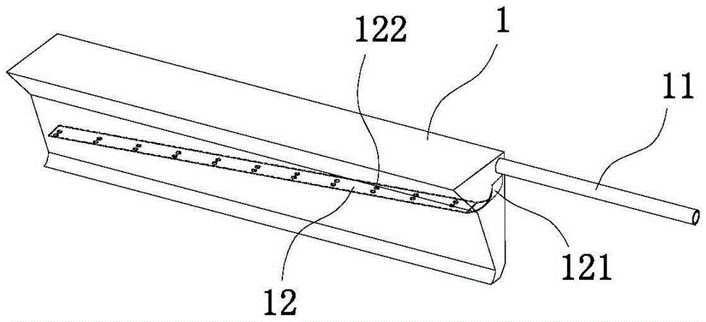
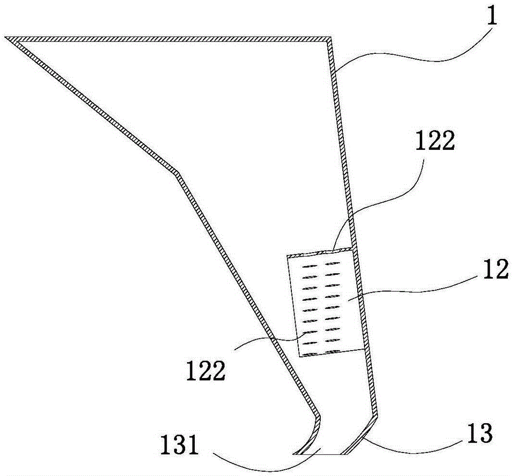
[0013] Such as figure 1 , figure 2 As shown, the oil nozzle structure of the material belt oiling in this embodiment includes the oil nozzle body 1, the oil nozzle body 1 is placed above the material belt, and the material belt is placed on the conveyor belt; the oil nozzle body 1 is a shell structure with a large upper end and a small lower end , the outer side of its upper end has an oil pipe 11 communicating with the oil tank, and its inner wall is inclined and fixedly connected with an oil guide plate 12. The high end of the oil guide plate 12 has an arc-shaped oil guide area 121 and is located below the oil inlet of the oil pipe 11. A plurality of oil leakage holes 122 are evenly distributed on the plate 12; the lower end of the oil nozzle body 1 has an oil guide part 13 bent toward the conveying direction of the strip, and the oil ...


PUM


Abstract

The invention relates to a nozzle structure for daubing a material strap with oil. The nozzle structure comprises a nozzle body; the nozzle body is arranged above the material strap; the nozzle body is of a shell structure of which the upper end is large and the lower end is small; an oil pipe communicated with an oil tank is arranged at the outer side of the upper end of the nozzle body; the inner wall of nozzle body is obliquely and fixedly connected with an oil guide plate; the high end of the oil guide plate is provided with an arc-shaped oil guide area and located below the oil inlet of the oil pipe; a plurality of oil leak holes are evenly distributed in the oil guide plate; the lower end of the nozzle body is provided with an oil guide part bent to the conveying direction of the material strap; the oil guide part is provided with a falling oil groove. According to the nozzle structure disclosed by the invention, oil flow is evenly guided to drop to the oil guide part by the oil guide plate; the material strap is evenly daubed with oil drops by the oil guide part through the falling oil groove; the daubing evenness of the nozzle structure is high; the falling oil width is limited by the width of the falling oil groove, and therefore the condition that the oil drops drop out of the material strap to cause pollution is avoided.

Description

technical field [0001] The invention relates to the technical field of stamping machinery and equipment, in particular to an oiling device for stamping strips. Background technique [0002] At present, when producing stamped products, it is necessary to spray stamping oil on the strip to facilitate stamping. In the prior art, the commonly used oil spraying methods basically include dripping, oiling, and spraying. The advantage of dripping operation is that its pollution is small, and the oil droplets will not drip to the outside of the material belt. Uneven application; during oiling operation, oil the upper and lower sides of the material belt after dipping a felt roller in oil. The material belt sprays the oil mist directly, which has the advantage of relatively uniform application, but the disadvantage is that the distance between the nozzle and the material belt is relatively large, and the oil mist spreads greatly during spraying, and the oil mist is not easy to adhere...

Claims


Application Information

Patent Timeline
Patent Type & Authority Patents(China)
IPC IPC(8): B05B1/14B05B15/04
CPCB05C5/0254
Inventor 孙毅刚
Owner 张学义
Why Eureka
Try Eureka