

Through type continuous folded plate structure suitable for tail edge part of turbine blade
A technology of turbine blade and folded plate structure, which is applied to the supporting elements of blades, engine elements, machines/engines, etc., can solve the problems of large flow loss, low outlet turbulence, and difficulty in achieving uniform and stable inlet airflow.
- Summary
- Abstract
- Description
- Claims
- Application Information
AI Technical Summary
Problems solved by technology
Method used
Image

Examples
Embodiment Construction
[0025] The present invention will be further explained below in conjunction with the accompanying drawings.
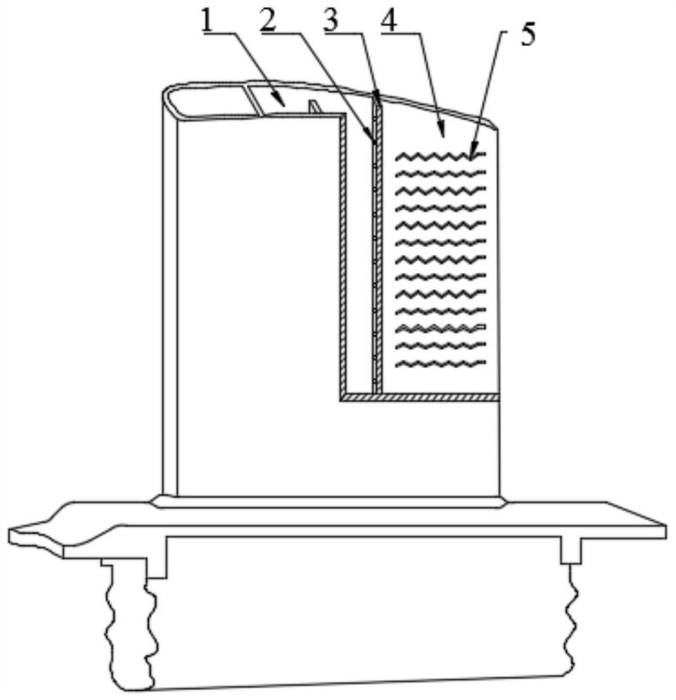
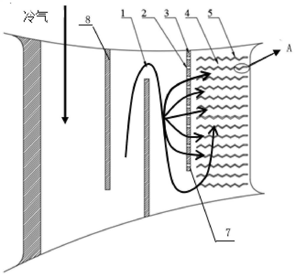
[0026] Such as Figures 1 to 3 As shown, a through-type continuous folded plate structure suitable for the trailing edge of the turbine blade of the present invention includes a U-shaped cooling channel 1 and a cooling cavity 4 for the trailing edge of the blade, and the U-shaped cooling channel is located at the end of the blade. The leading edge and the middle part, the blade trailing edge cooling cavity 4 is located at the blade trailing edge, and the U-shaped cooling channel position 1 is separated from the blade trailing edge cooling cavity 4 by a side wall surface 7, and the bottom of the side wall surface 7 is provided with an opening, which serves as At the outlet of the U-shaped cooling passage 1, a number of air holes 3 are opened in the side wall surface 7, and multiple rows of through-type continuous folded plates 5 are arranged in the cooling chamber 4 of ...
PUM
| Property | Measurement | Unit |
|---|---|---|
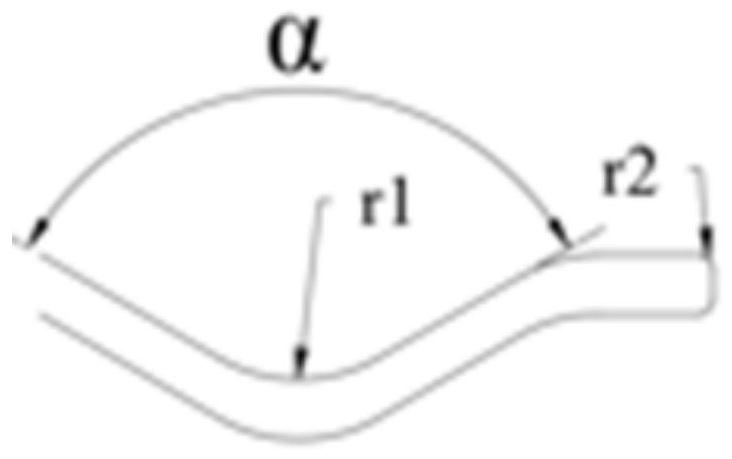
| Angle | aaaaa | aaaaa |
| Radius | aaaaa | aaaaa |
Abstract
Description
Claims
Application Information