
Steam supplementing chamber structure of steam turbine cylinder

A steam turbine and cylinder technology, applied in the field of steam supplement chamber structure, can solve the problems of increasing the loss of the downstream static cascade, increasing the vibration of the rotor, and affecting the efficiency of the unit, so as to facilitate popularization and application, reduce disturbance, and reduce the degree of mutual mixing Effect

Active Publication Date: 2021-05-25
DONGFANG TURBINE CO LTD
View PDF15 Cites 1 Cited by
  • Summary
  • Abstract
  • Description
  • Claims
  • Application Information

AI Technical Summary

Problems solved by technology

[0003] High-power steam turbines often introduce supplementary steam flow from the supplementary steam chamber of the cylinder to increase output power, but the steam entering the steam turbine through the supplementary steam chamber (called supplementary steam) will cause damage to the original main steam (main steam flow) in the steam turbine. Disturbance, on the one hand, there will be a mixing loss with the original main steam, which will change the distribution of the inlet steam parameters of the downstream static cascade along the circumferential direction, resulting in inhomogeneity, increasing the loss of the downstream static cascade, and affecting the efficiency of the unit. Will increase the vibration of the rotor

Method used


Image

  • Steam supplementing chamber structure of steam turbine cylinder
  • Steam supplementing chamber structure of steam turbine cylinder
  • Steam supplementing chamber structure of steam turbine cylinder

Examples


Embodiment Construction

[0016] All features disclosed in this specification, or steps in all methods or processes disclosed, may be combined in any manner, except for mutually exclusive features and / or steps.

[0017] Any feature disclosed in this specification, unless specifically stated, can be replaced by other alternative features that are equivalent or have similar purposes. That is, unless expressly stated otherwise, each feature is one example only of a series of equivalent or similar features.

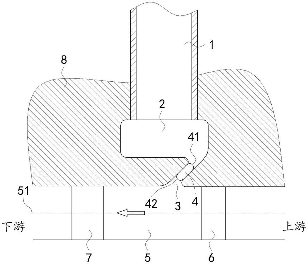
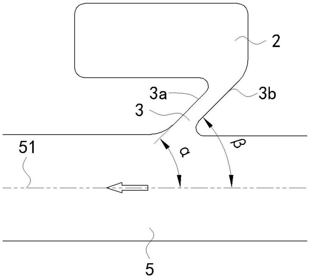
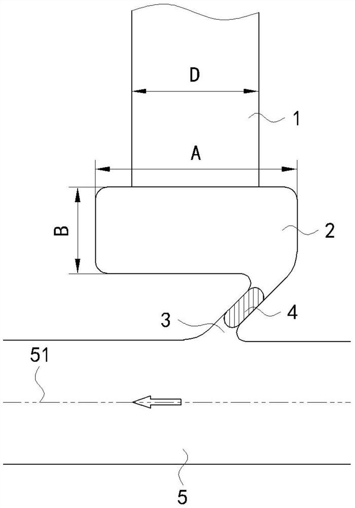
[0018] like Figure 1 to Figure 4 As shown, the air intake chamber structure of a steam turbine cylinder in this embodiment includes an annular main steam flow channel 5 formed between the cylinder 8 and the rotor. In the circumferential direction of the cylinder 8, the cylinder There is a mixing ring cavity 2 inside, the outside of the mixing ring cavity 2 is connected with the supplementary steam channel 1, and the inside of the mixing ring cavity 2 is connected with the main steam flow channel 5 t...


PUM


Abstract

The invention discloses a steam supplementing chamber structure of a steam turbine cylinder, and belongs to the technical field of steam turbines. The steam supplementing chamber structure of the steam turbine cylinder comprises an annular main steam flow channel formed between the cylinder and a rotor; a mixing ring cavity is formed in the cylinder in the circumferential direction of the cylinder; the outer side of the mixing ring cavity communicates with a steam supplementing channel; the inner side of the mixing ring cavity communicates with the main steam flow channel through a flow guide ring cavity; the flow guide ring cavity inclines towards the main steam flow flowing direction of the main steam flow channel; a plurality of flow guide partition plates are arranged in the flow guide ring cavity in the circumferential direction of the flow guide ring cavity; and the flow guide ring cavity is divided into a plurality of sub-cavities by the plurality of flow guide partition plates. According to the invention, the mixing degree and the mixing loss of the supplemented steam and the main steam flow can be reduced, and the influence of the supplemented steam on the stability of the rotor can be reduced.

Description

technical field [0001] The invention relates to a steam supplement chamber structure of a steam turbine cylinder, belonging to the technical field of steam turbines. Background technique [0002] As the main power device, the steam turbine is widely used in various fields. Therefore, high efficiency and cleanliness have become the key indicators for the operation of the steam turbine. It is widely used in high-power units. [0003] High-power steam turbines often introduce supplementary steam flow from the supplementary steam chamber of the cylinder to increase output power, but the steam entering the steam turbine through the supplementary steam chamber (called supplementary steam) will cause damage to the original main steam (main steam flow) in the steam turbine. Disturbance, on the one hand, there will be a mixing loss with the original main steam, which will change the distribution of the inlet steam parameters of the downstream static cascade along the circumferential...

Claims


Application Information

Patent Timeline
Patent Type & Authority Applications(China)
IPC IPC(8): F01D17/16F01D25/00
CPCF01D17/16F01D25/00
Inventor 钟主海魏艳江生科孙奇杜小琴平艳杨长柱钟刚云邹昆
Owner DONGFANG TURBINE CO LTD
Learn More