Device for freely separating cold and hot fluid media

A technology of fluid medium and separation device, which is applied in the field of energy storage, and can solve problems such as the difficulty in realizing the automatic rise and fall of the floating heat shield, the continuous response adjustment of the buoyancy of the floating heat shield, and the unavoidable disturbance and mixing of hot and cold fluids. , to achieve remarkable energy saving effect, simple structure and low cost

Active Publication Date: 2019-11-22
SHANDONG UNIV
View PDF8 Cites 1 Cited by
  • Summary
  • Abstract
  • Description
  • Claims
  • Application Information

AI Technical Summary

Problems solved by technology

When the cross-section of the tank is large, a multi-circle pipe water distributor is used, and the opening spacing of the water distribution pipes is not equal, so as to achieve equal water distribution areas of the water distribution pipes, thereby reducing disturbance and achieving approximately uniform low-speed flow, but the water distribution pipes and openings The hole processing is complicated, but it is difficult to significantly reduce the thickness of the thermocline layer and improve the efficiency of the heat storage system from the optimization of the water distributor
[0006] Chinese patent 201210379993.9 proposes a single-tank heat storage system and a single-tank heat storage method. A floating heat shield and a counterweight device are introduced into the heat storage tank. The system relies on a large number of pumps and valves, the mechanism is complex, and the floating heat shield The gravity is fixed, but the temperature change of the heat storage fluid causes the density to change, which in turn leads to continuous changes in the buoyancy of the fluid to the floating heat shield. The counterweight of the floating heat shield is fixed, so it is difficult to achieve continuous response adjustment to the buoyancy of the floating heat shield. It is not easy to realize the automatic rising and falling of the floating heat shield
Obviously, it is not suitable for cold storage tanks, but for floating plates that meet both density requirements and heat insulation, it poses challenges to material properties and preparation processes, and the patent does not mention relevant material details
In addition, the size of the gap between the floating plate and the inner wall of the shell is not described, and the sealing is not described, which inevitably produces disturbance and mixing of hot and cold fluids

Method used


Image

  • Device for freely separating cold and hot fluid media
  • Device for freely separating cold and hot fluid media
  • Device for freely separating cold and hot fluid media

Examples


Embodiment 1

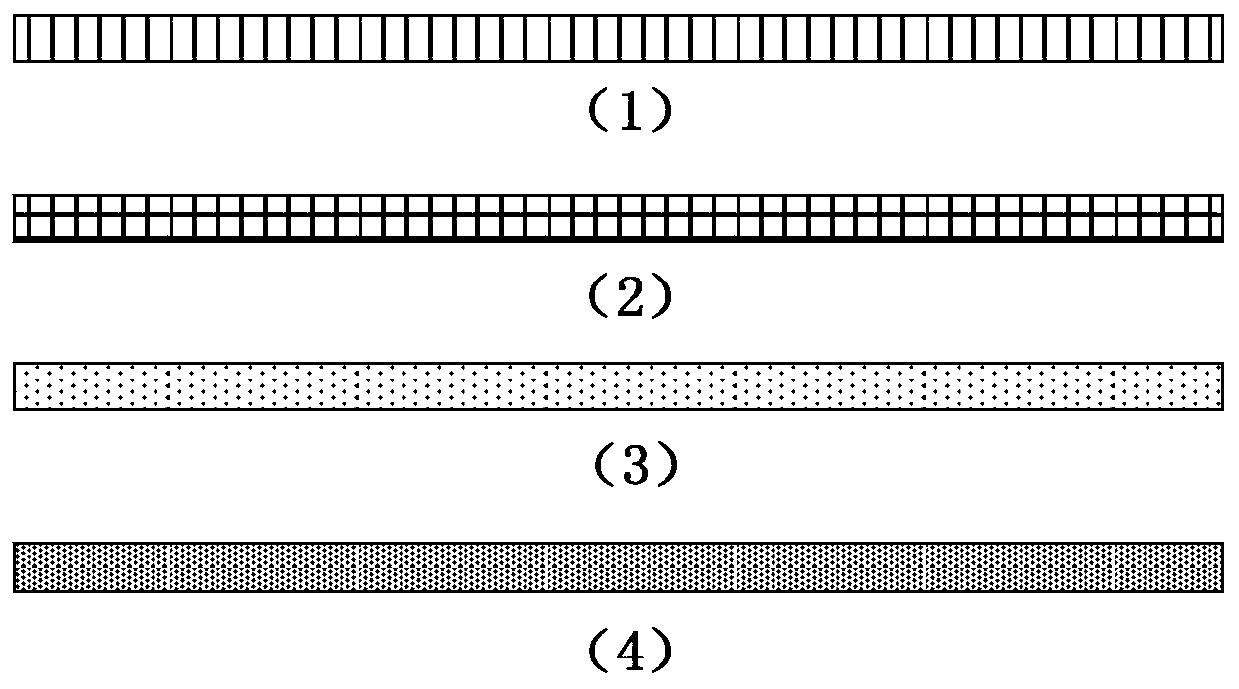
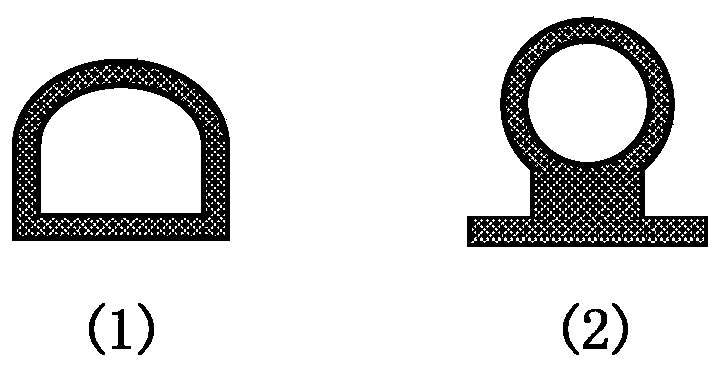
[0053] The heat insulation board is made of polycarbonate endurance board, round, and the structure is a two-layer hollow heat insulation board, such as figure 2 As shown in (2), the thickness of the skeleton solid board is 1.5mm, and the thickness of the heat insulation board is 15mm. image 3 As shown in (2), adopt hot melt adhesive, select NdFeB magnet (type N45M, density 7.5g / cm 3 ) Magnetic rod Φ5×50mm (diameter×length), heat-resistant temperature 100°C, and the sealing strip around the heat shield is arranged to fill the cavity continuously, such as Figure 4 Shown in (1). According to the density of hot and cold water in the heat storage tank, the gravity and buoyancy of the polycarbonate endurance board, and the filling amount selected in the experiment, the friction between the sealing strip and the wall surface of the heat insulation device under the action of buoyancy, gravity and magnetic force can make it in the cold and hot fluid The interface, and moves up an...

Embodiment 2

[0055] The heat insulation board is made of polycarbonate endurance board, round, and the structure is a single-layer hollow heat insulation board, such as figure 2 As shown in (1), the thickness of the skeleton solid board is 2mm, the thickness of the heat insulation board is 10mm, and the edge adopts silicone foam D-shaped sealing strip, such as image 3 As shown in (1), use hot melt adhesive, select NdFeB magnet (type N45, density 7.5g / cm 3 ) magnetic strip 100×10×2mm (length×width×thickness), heat-resistant temperature 80°C, and the cavity filling arrangement of the sealing strip around the heat shield, such as Figure 4 Shown in (2). According to the density of hot and cold water in the heat storage tank, the gravity and buoyancy of the polycarbonate endurance board, the filling amount is selected in the experiment, so that the friction between the sealing strip and the wall of the heat insulation device under the action of buoyancy, gravity and magnetic force can make ...

Embodiment 3

[0057] The heat insulation board is made of low-density silica gel foam porous board, round, with a structure such as figure 2 As shown in (3), the thickness of the heat insulation board is 10mm, and the edge adopts a silicone foam D-shaped sealing strip, such as image 3 As shown in (1), use hot melt adhesive to paste and fix the sealing strip and the heat insulation board body, and select NdFeB magnets (model N45, density 7.5g / cm 3 )Magnetic strip 50×10×2mm (length×width×thickness) with heat resistance temperature of 80°C, the cavity of the sealing strip around the heat shield is filled and arranged at intervals, such as Figure 4 Shown in (3). According to the density of hot and cold water in the heat storage tank, the gravity and buoyancy of the low-density silica gel foam porous plate, and the filling amount selected in the experiment, the friction between the sealing strip and the wall surface of the heat insulation device under the action of buoyancy, gravity, and mag...


PUM


Abstract

The invention discloses a device for freely separating cold and hot fluid media. The device comprises a tank body which is cylindrical and is vertically arranged, and a heat insulation plate which isof a plate structure and is arranged on the horizontal section of the tank body, wherein a hot fluid inlet and a cold fluid inlet are formed in the upper end and the lower end of the tank body correspondingly; a storage space for cold fluid and hot fluid is provided; the side wall of the tank body is provided with at least one adsorption layer; the adsorption layer is made of a ferromagnetic material or iron; the heat insulation plate is matched with the horizontal section of the tank bod in shape and area; a sealing strip is arranged in the circumferential direction of the heat insulation plate; the sealing strip is of a hollow structure, and the hollow position is evenly filled with adsorption blocks; the adsorption blocks are ferromagnetic material blocks or iron blocks; and the adsorption layer and the adsorption blocks generate attractive force. The device can freely isolate the cold and hot media, the thickness of an inclined temperature layer is significantly reduced, mixing ofhigh-temperature and low-temperature media is effectively suppressed, and the device does not require additional active support, and is stable and reliable in operation, low in cost, significant in energy-saving effect and easy to maintain.

Description

technical field [0001] The invention relates to the technical field of energy storage, in particular to a device for freely separating cold and hot fluid media. Background technique [0002] The information disclosed in this background section is only intended to increase the understanding of the general background of the present invention, and is not necessarily taken as an acknowledgment or any form of suggestion that the information constitutes the prior art already known to those skilled in the art. [0003] Heat storage or cold storage systems can be used for unit peak regulation, cogeneration of heat and power, consumption of wind power generation, efficient use of solar heat, and industrial waste heat. It is of great significance for peak shifting, multi-energy complementary, energy saving, and energy utilization efficiency . [0004] Heat storage and cold storage water tanks are mainly used in the field of sensible heat heating and cooling. Using the principle of di...

Claims


Application Information

Patent Timeline
Patent Type & Authority Applications(China)
IPC IPC(8): F28D20/00
CPCF28D20/0039F28D2020/0091Y02E60/14
Inventor 韩奎华高明齐建荟
Owner SHANDONG UNIV
Why Eureka
Try Eureka