
Tank and liquid droplet jetting apparatus connected to the same

Active Publication Date: 2015-12-17
BROTHER KOGYO KK
View PDF1 Cites 9 Cited by
  • Summary
  • Abstract
  • Description
  • Claims
  • Application Information

AI Technical Summary

Benefits of technology

The invention described in this patent text uses a configuration to show the level of liquid in a container through a wall. This allows the user to see the need for replenishing the liquid through the outlet, while preventing air from mixing in. The technical effect of this invention is to provide an efficient and effective way to monitor liquid levels and promptly replenish them.

Problems solved by technology

It is difficult, however, to make a user recognize that the ink needs to be replenished or refilled in a state that the ink is still stored in the space between the liquid lead-out section and the bottom surface of the ink tank.

Method used


Image

  • Tank and liquid droplet jetting apparatus connected to the same
  • Tank and liquid droplet jetting apparatus connected to the same
  • Tank and liquid droplet jetting apparatus connected to the same

Examples


Embodiment Construction

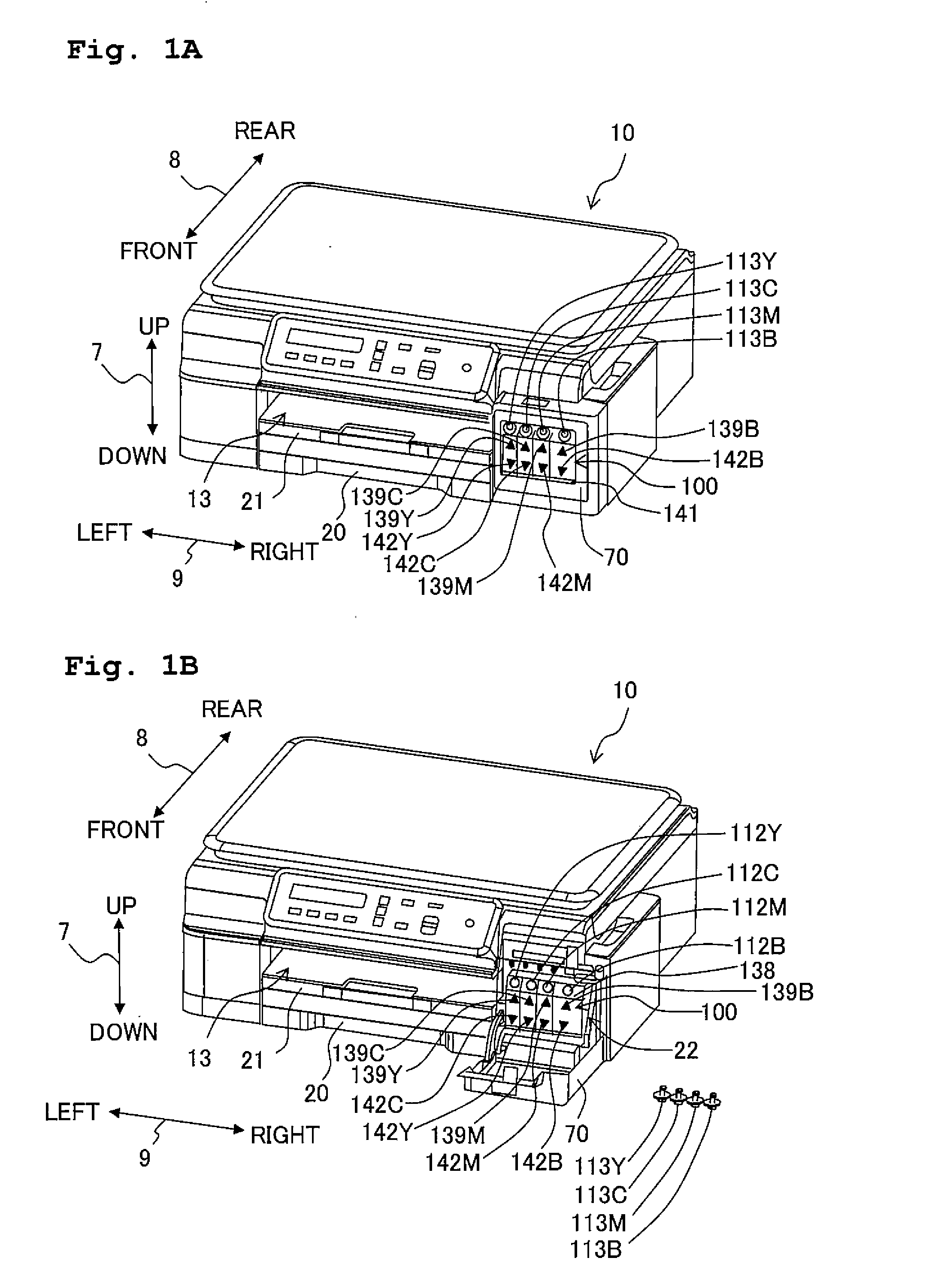
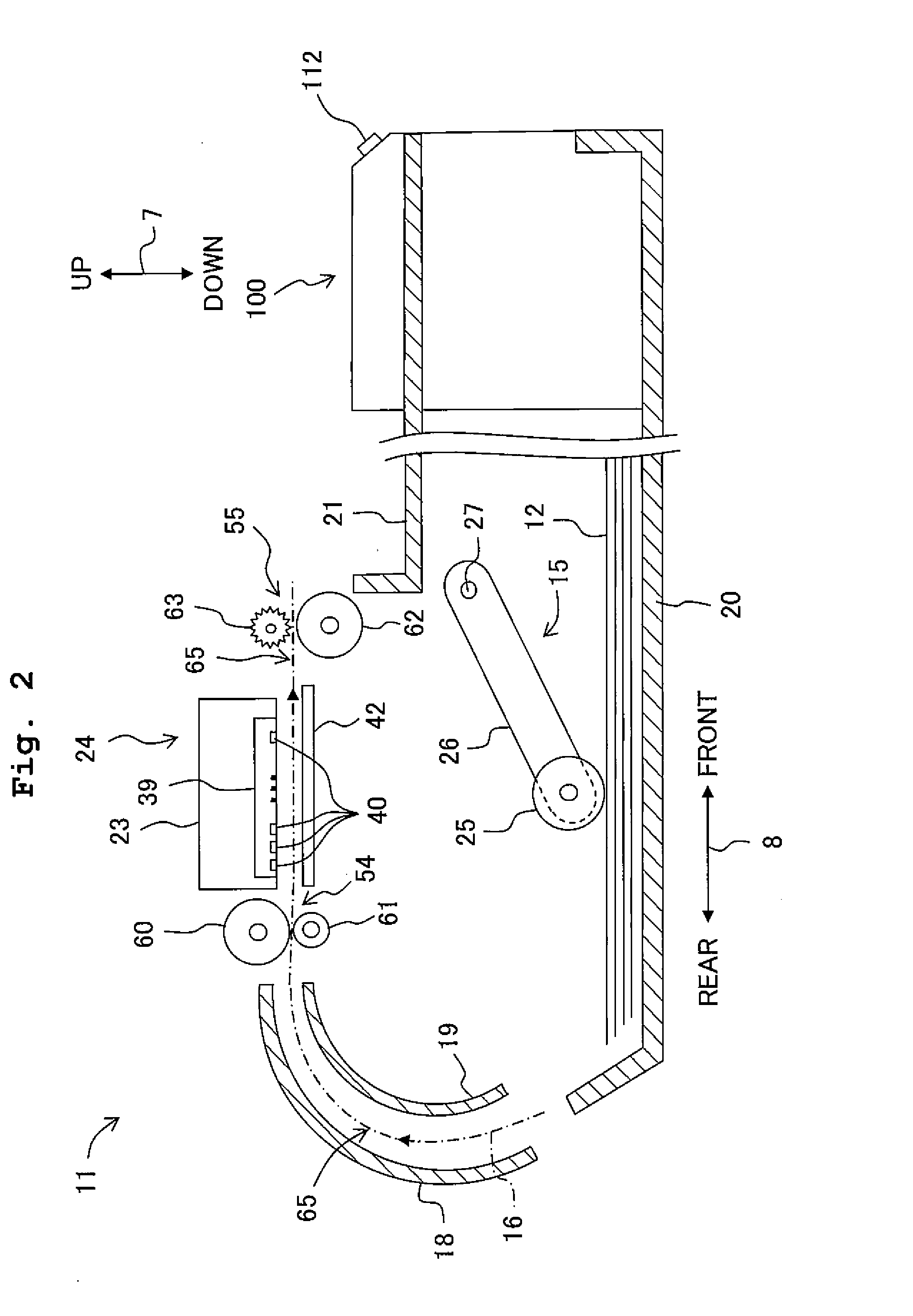
[0025]An embodiment of the present teaching will be described below. Note that, however, the embodiment described below is merely an example of the present teaching; it goes without saying that it is possible to make any appropriate changes in the embodiment of the present teaching without departing from the gist and scope of the present teaching. In the following description, upward and downward are each a component of an up-down direction 7 and are opposite to each other; leftward and rightward are each a component of a left-right direction 9 and are opposite to each other; and frontward and rearward are each a component of a front-rear direction 8 and are opposite to each other. Further, in the embodiment, the up-down direction 7 corresponds to the vertical direction, and each of the front-rear direction 8 and the left-right direction 9 corresponds to the horizontal direction.

[0026]Furthermore, the up-down direction 7 is defined with a state that a multi-function peripheral 10 is...


PUM


Abstract

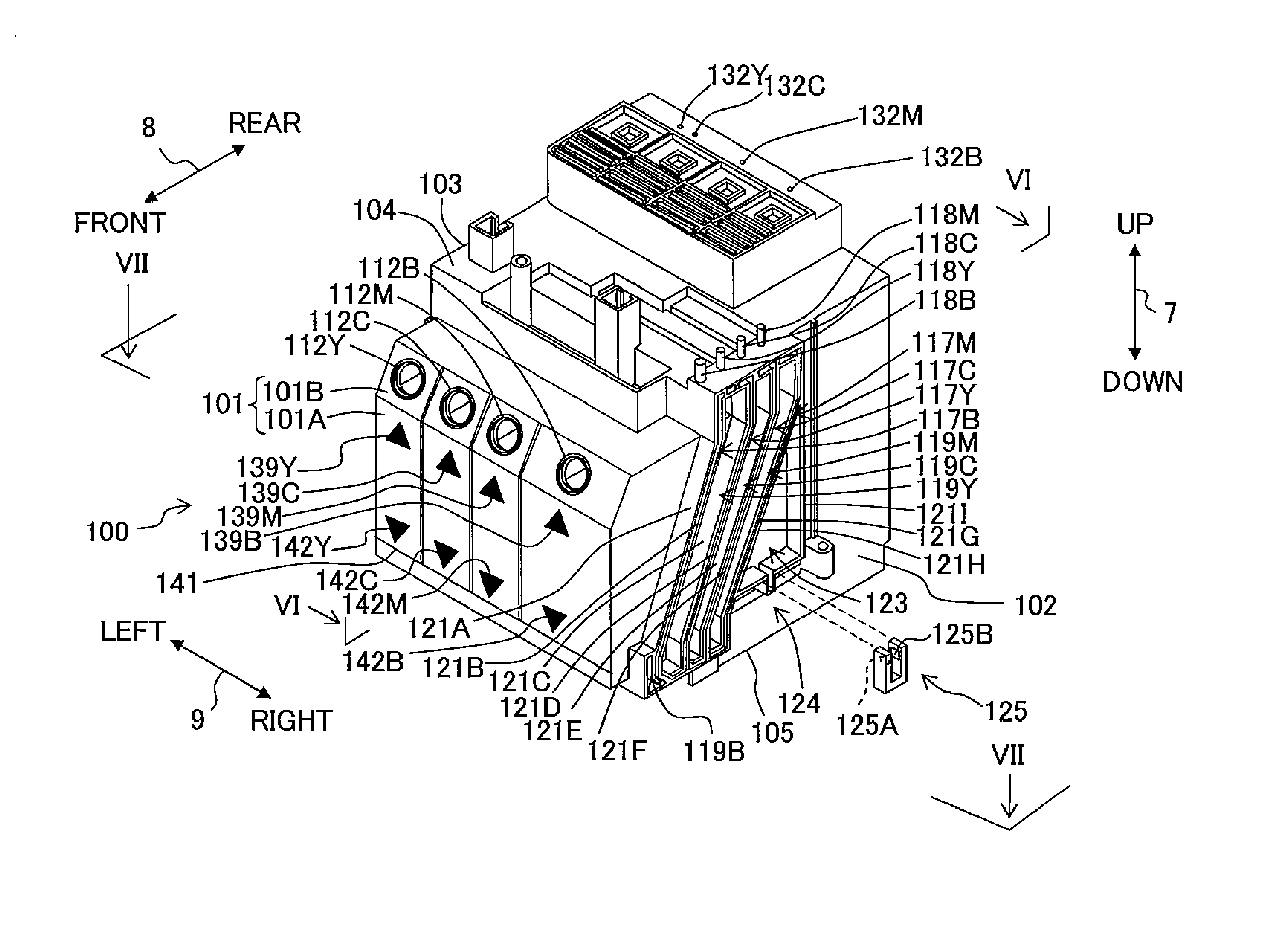
There is provided a tank including: a wall defining a liquid storage chamber, the wall including: an upper wall defining an upper end of the liquid storage chamber, a lower wall defining a lower end of the liquid storage chamber, and an erected wall between the upper wall and the lower wall and through which the liquid inside the liquid storage chamber is visible from outside of the tank; an inlet penetrating through the upper wall or the erected wall; and an outlet, wherein the lower wall includes an upper stage wall making contact with the erected wall; a lower stage wall located at a position separated and away from the erected wall and below the upper stage wall; and a connecting wall connecting the upper and lower stage walls; and the outlet is disposed below the upper stage wall.

Description

CROSS REFERENCE TO RELATED APPLICATION[0001]The present application claims priority from Japanese Patent Application No. 2014-121856 filed on Jun. 12, 2014 the disclosure of which is incorporated herein by reference in its entirety.BACKGROUND[0002]1. Field of the Invention[0003]The present invention relates to a tank configured to supply a liquid to liquid consuming section, and a liquid droplet jetting apparatus including the tank.[0004]2. Description of the Related Art[0005]Conventionally, there is known an ink jet printer, etc., as an example of a liquid consuming apparatus provided with a liquid consuming section configured to consume a liquid stored in a liquid storage chamber. For example, there is known an ink jet printer provided with an ink tank which stores an ink, and a liquid jetting section which jets the ink supplied from the ink tank via a liquid delivery (lead-out) section. Further, the ink tank is configured such that the liquid can be replenished (refilled) to the ...

Claims


Application Information

Patent Timeline
IPC IPC(8): B41J2/175
CPCB41J2/17513B41J2/1752B41J2/175B41J2/17503B41J2/17553
Inventor IGARASHI, AKINORI
Owner BROTHER KOGYO KK
Learn More