Seawater desalination system and energy exchange chamber

a technology of energy exchange chamber and seawater desalination system, which is applied in the direction of membranes, specific water treatment objectives, reverse osmosis, etc., can solve the problems of large impact on the operational cost of the seawater desalination system, more than half of the electric expenses, and the replacement cycle of the reverse-osmosis membrane itself can be prolonged, and the performance is sufficient.

Active Publication Date: 2015-04-21
EBARA CORP
View PDF11 Cites 10 Cited by
  • Summary
  • Abstract
  • Description
  • Claims
  • Application Information

AI Technical Summary

Benefits of technology

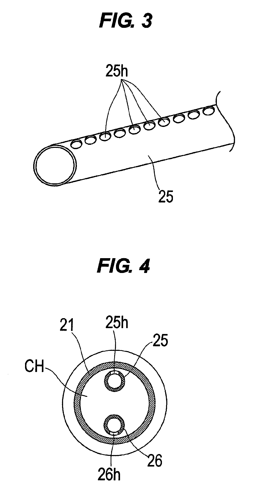
[0024]According to the present invention, connecting portions of the connecting member for connecting the distributors have substantially triangular cross-sections whose cross-sectional areas are gradually enlarged so as to be closer to outer diameters of the distributors. Thus, any changes in the boundary when the boundary is positioned above the lower end of the seawater distributor or below the upper end of the concentrated seawater distributor can be reduced, and thus turbulence of the boundary can be suppressed.
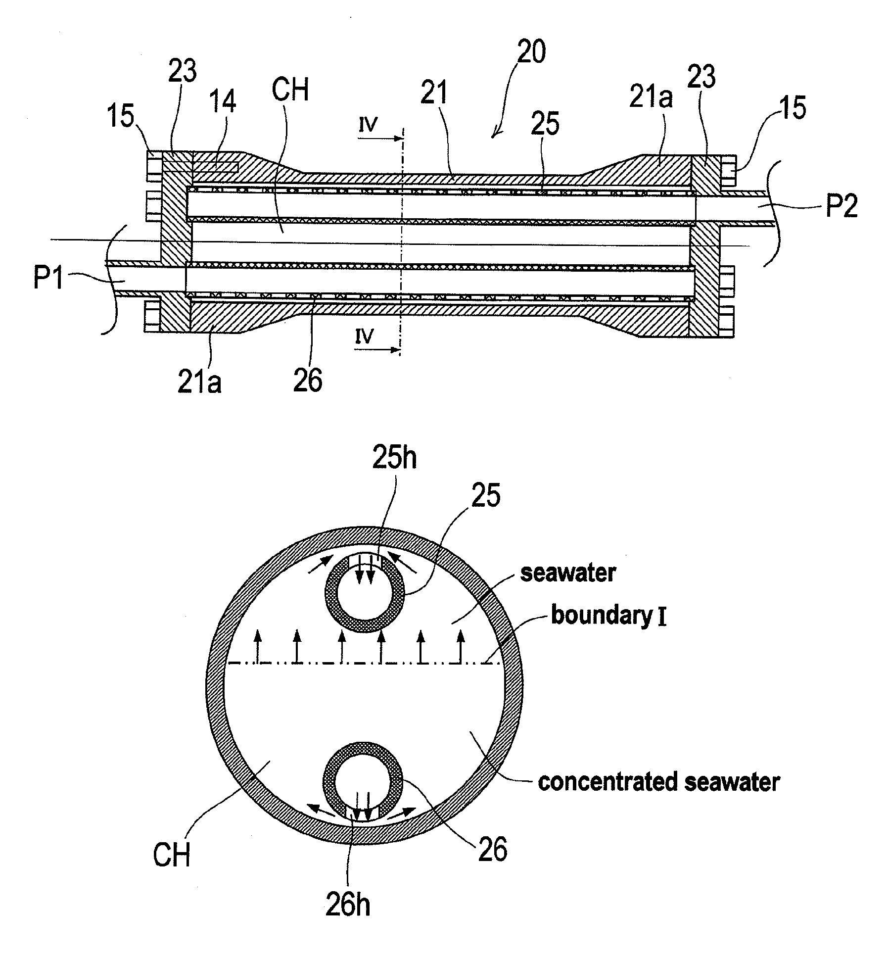
[0026]According to the present invention, two perforated plates for connecting surfaces of both sides of the seawater distributor and an inner circumferential surface of the chamber are provided, and two perforated plates for connecting surfaces of both sides of the concentrated seawater distributor and the inner circumferential surface of the chamber are provided. Thus, a first space formed by the concentrated seawater distributor and the two perforated plates, a third space formed by the seawater distributor and the two perforated plates and a second space between the first space and the third space are defined. With this structure, the concentrated seawater which flows in from the concentrated seawater distributor enters the first space, and passes through the perforated plates from the first space. At this time, the flow velocity of the concentrated seawater is uniformized by the perforated plates and the concentrated seawater whose flow velocity has been uniformized flows in the second space. With this action, the concentrated seawater in the second space flows upwardly more uniformly, and thus a pressure can be transmitted from the high-pressure concentrated seawater to the seawater while turbulence of the boundary is suppressed and mixing of the concentrated seawater and the seawater is suppressed. On the other hand, when the seawater which has been pushed up passes through the perforated plates from the second space, the flow velocity of the seawater is uniformized by the perforated plates. Then, the seawater whose flow velocity has been uniformized by the perforated plates flows in the third space, and then flows out from the upward through-holes formed in the seawater distributor.
[0027]According to the present invention, the perforated plate comprises a punching plate having a plurality of holes formed in a plate. The diameter of the hole is in the range of 3 to 10 mm. A porosity representing an area of holes with respect to an entire area of the plate is in the range of 30 to 60%. The perforated plate is configured to have small pressure loss generated when the fluid passes therethrough and to have flow uniformizing effect.
[0031]According to the present invention, two perforated plates are arranged one above the other at intervals so as to extend in a horizontal direction in the interior of the chamber, and thus the chamber is partitioned from the bottom upwardly into a first space, a second space and a third space by the two perforated plate. The concentrated seawater which has flowed in from the concentrated seawater port spreads in the first space, and flows in the second space after the flow of the concentrated seawater is uniformly regulated by the lower perforated plate. The concentrated seawater flows upward so as to push up the seawater existing thereon in the second space. At this time, the flow of the concentrated seawater whose direction and velocity have been uniformized is formed by the lower perforated plate, and thus mixing of the concentrated seawater and the seawater is suppressed in the boundary in the second space. The same flow regulating effect is produced in the case where the seawater flows in the third space from the upper seawater port and flows in the second space from the third space through the upper perforated plate.
[0040]According to the present invention, the following effects can be achieved.
[0042]2) Because mixing of the concentrated seawater and the seawater in the chamber due to turbulent flow diffusion can be suppressed and the seawater having a high salt content is not delivered to the reverse-osmosis membrane-separation apparatus, the reverse-osmosis membrane-separation apparatus can provide sufficient performance and the replacement cycle of the reverse-osmosis membrane itself can be prolonged.

Problems solved by technology

The largest operational cost in the seawater desalination system is energy cost for pressurizing the pretreated seawater up to such a pressure as to overcome the osmotic pressure, i.e. up to the reverse-osmosis pressure.
That is, the operational cost of the seawater desalination system is greatly affected by pressurizing energy of the seawater by the high-pressure pump.
Specifically, more than half of the electric expenses as the highest cost in the seawater desalination system are consumed to operate the high-pressure pump for pressurizing the seawater.
Further, the inner diameter of the long chamber is required to be machined with high accuracy so as to fit with the outer shape of the piston, and thus machining cost is very expensive.
As a result, the present inventors have learned that when the longitudinal direction of the chamber is placed horizontally, in the case where there is a difference in specific gravity, a problem arises.

Method used


Image

  • Seawater desalination system and energy exchange chamber
  • Seawater desalination system and energy exchange chamber
  • Seawater desalination system and energy exchange chamber

Examples


Embodiment Construction

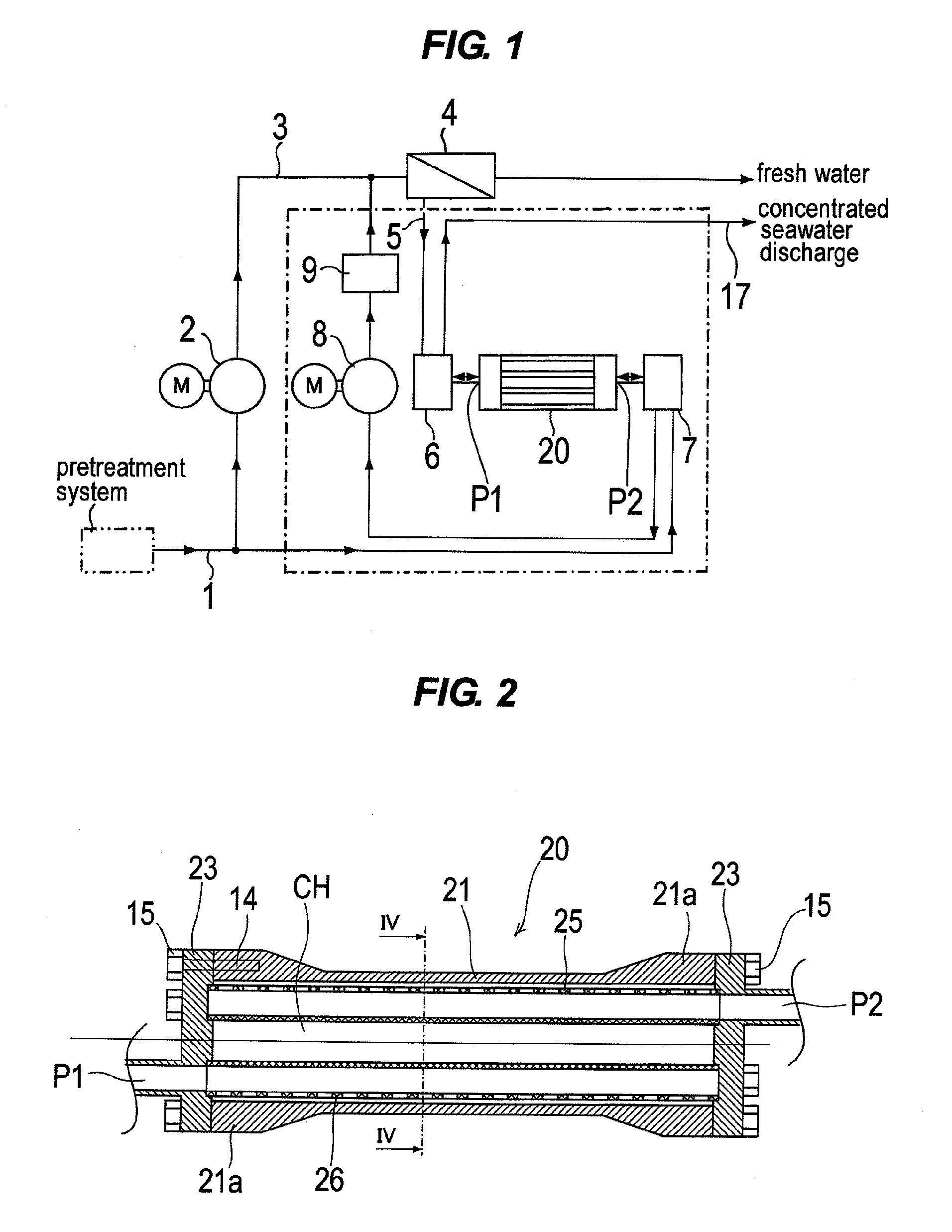
[0062]A seawater desalination system according to preferred embodiments of the present invention will be described in detail below with reference to FIGS. 1 through 18. Like or corresponding parts are denoted by like or corresponding reference numerals in FIGS. 1 through 18 and will not be described below repetitively.

[0063]FIG. 1 is a schematic view showing a configuration example of a seawater desalination system according to the present invention. As shown in FIG. 1, seawater pumped into the seawater desalination system by an intake pump (not shown) is processed to have certain water qualities by a pretreatment system, and then the pretreated seawater is delivered via a seawater supply line 1 into a high-pressure pump 2 that is driven by a motor M. The seawater which has been pressurized by the high-pressure pump 2 is supplied via a discharge line 3 to a reverse-osmosis membrane-separation apparatus 4 having a reverse-osmosis membrane (RO membrane). The reverse-osmosis membrane-s...


PUM

PropertyMeasurementUnit
diameteraaaaaaaaaa
porosityaaaaaaaaaa
specific gravityaaaaaaaaaa

Abstract

An energy exchange chamber is used for exchanging pressure energy between concentrated seawater discharged from a reverse-osmosis membrane-separation apparatus and a part of seawater to be treated by the reverse-osmosis membrane separation apparatus in a seawater desalination system. The energy exchange chamber includes a concentrated seawater distributor communicating with a concentrated seawater port and configured to distribute a flow of concentrated seawater all over a horizontal plane of an interior of a chamber, and a seawater distributor communicating with a seawater port and configured to distribute a flow of seawater all over the horizontal plane of the interior of the chamber. The concentrated seawater and the seawater introduced into the chamber are brought into direct contact with each other over the horizontal plane of the interior of the chamber to exchange pressure energy between the concentrated seawater and the seawater introduced into the chamber.

Description

CROSS REFERENCE TO RELATED APPLICATIONS[0001]This document claims priority to Japanese Application Number 2011-095704, filed Apr. 22, 2011, the entire contents of which are hereby incorporated by reference.BACKGROUND OF THE INVENTION[0002]1. Field of the Invention[0003]The present invention relates to a seawater desalination system for desalinating seawater by removing salinity from the seawater and an energy exchange chamber (pressure exchange chamber) of an energy recovery device which is preferably used in the seawater desalination system.[0004]2. Description of the Related Art[0005]Conventionally, as a system for desalinating seawater, there has been known a seawater desalination system in which seawater passes through a reverse-osmosis membrane-separation apparatus to remove salinity from the seawater. In the seawater desalination system, the intake seawater is processed to have certain water qualities by a pretreatment system, and the pretreated seawater is delivered into the ...

Claims


Application Information

Patent Timeline
Patent Type & Authority Patents(United States)
IPC IPC(8): B01D61/06C02F1/44C02F1/00C02F103/08
CPCC02F1/441B01D61/06C02F1/006B01D2313/246C02F2103/08C02F2201/003C02F2301/022C02F2303/10Y02A20/131Y02W10/30
Inventor TAKAHASHI, TAMAMIMAEDA, KAZUAKIGOTO, MASANORI
Owner EBARA CORP
Why Eureka
Try Eureka