Exhaust System for Steam Turbine

Active Publication Date: 2012-07-19
MITSUBISHI POWER LTD
View PDF10 Cites 10 Cited by
  • Summary
  • Abstract
  • Description
  • Claims
  • Application Information

AI Technical Summary

Benefits of technology

[0021]According to the present invention, an annular flow guide for high and/or intermediate turbines can be improved in perfor

Problems solved by technology

If an annular flow guide is excessively enlarged (elongated), the flow passage will be blocked to degrade performance.
Since the exhaust hood of high and intermediate pressure turbines has a shorte

Method used


Image

  • Exhaust System for Steam Turbine
  • Exhaust System for Steam Turbine
  • Exhaust System for Steam Turbine

Examples


first embodiment

—Configuration—

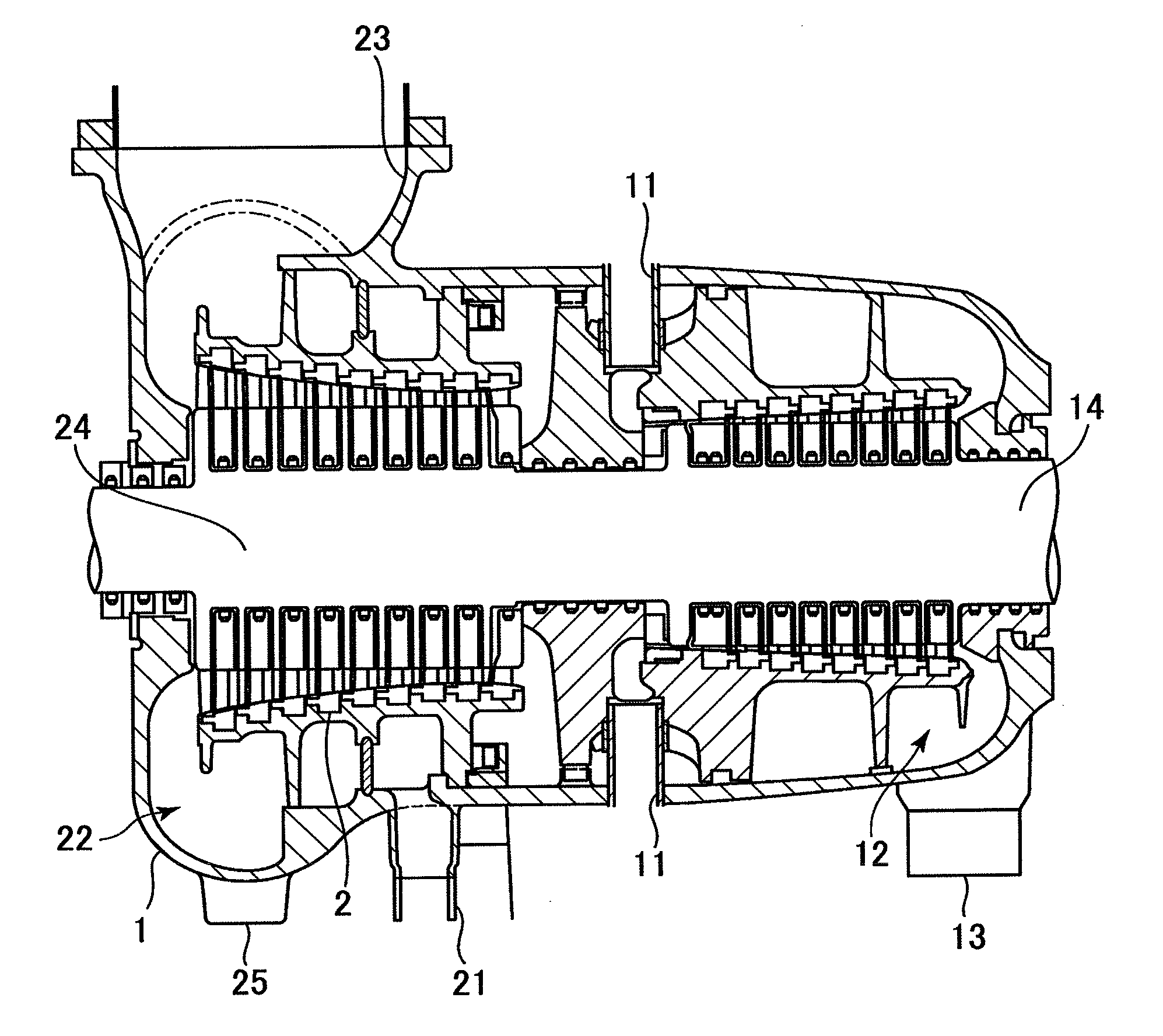
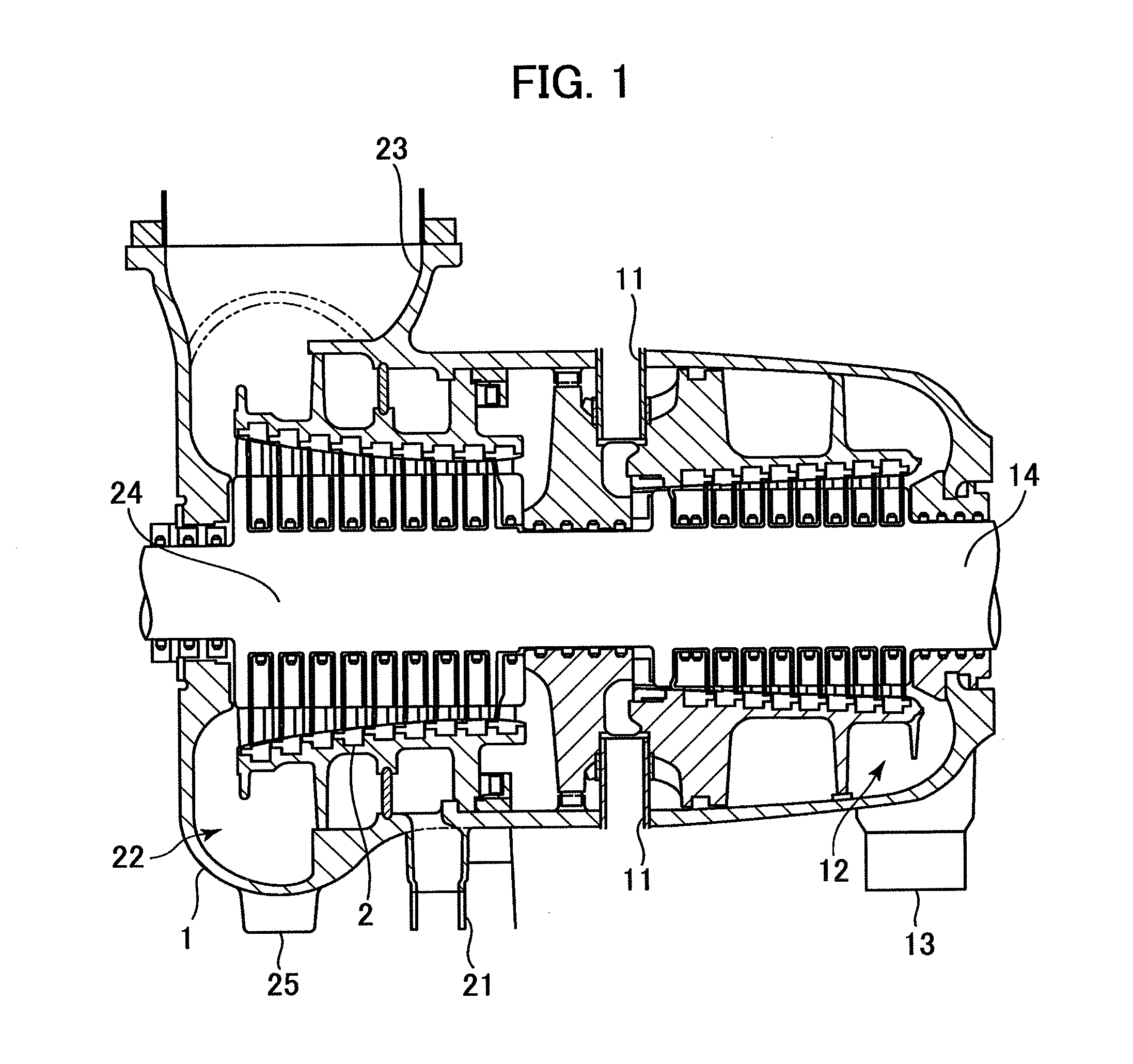
[0037]FIG. 1 is a cross-sectional view illustrating a schematic configuration of high and intermediate pressure portions of a steam turbine embodying the present invention. Steam first flows in from a high pressure inlet 11, performs work in a high pressure turbine stage 14, and flows out into a high pressure exhaust duct 13 via a high pressure exhaust hood 12. The steam flowing out from the high pressure exhaust hood 12 flows through the high pressure exhaust duct 13, a boiler (not shown) and a reheat inlet duct 21 and enters an intermediate turbine stage 24. After doing work at the intermediate turbine stage 24, the steam flows out into an intermediate exhaust duct 23 via an intermediate exhaust hood 22. On the other hand, the steam bled thorough a bleed pipe is led into a heater to be heated.

[0038]An exhaust system includes an inner casing 2 covering a turbine rotor 3 of the steam turbine and an outer casing 1 covering the inner casing 2.

[0039]The high pressure exh...

second embodiment

[0067]In the first embodiment, the portion of the flow guide with θ ranging from 100 to 180° was defined as the downstream flow guide portion 5d having a flow guide occupancy ratio of 0.7. Alternatively, the portion with 0 ranging from approximately 100 to 150°, the area corresponding to the joint portion with the exhaust duct 13, may be set as a most-downstream flow guide portion 5d1. The flow guide occupancy ratio of the most-downstream flow guide portion 5d1 may be set at 0.7.

[0068]FIG. 10 is a graph showing an example of a shape of the flow guide 5B. The flow guide occupancy ratio of the upstream flow guide portion 5u (θ=0 to 80°) is set at 0.4 and that of the most-downstream flow guide portion 5d1 (θ=100 to 150°) is set at 0.7. The flow guide occupancy ratio of the downstream flow guide portion 5d2 (θ=170 to 180°) is set at 0.4 and that of the intervals (θ=80 to 100° and 150 to 170°) varies continuously between 0.4 and 0.7. A transverse cross-sectional view of such flow guide 5...

third embodiment

[0070]The first and the second embodiments showed cases where the present invention is applied to an exhaust hood 12 having two exhaust ducts 13 at the downstream side. The present invention may also be applied to an exhaust hood 12 having one exhaust duct 13.

[0071]FIG. 12 is a graph showing an example of a shape of a flow guide 5C. The flow guide occupancy ratio of the upstream flow guide portion 5u (θ=0 to 120°) is set at 0.4 and that of the downstream flow guide portion 5d (θ=160 to)180° is set at 0.7. The flow guide occupancy ratio of the interval portion (θ=120 to 160°) between them varies continuously from 0.4 to 0.7. A transverse cross-sectional view of the flow guide 5C is shown in FIG. 13.

[0072]The third embodiment can also produce the same effect as that of the first embodiment.


PUM


Abstract

An exhaust system for a steam turbine provided with an improved annular flow guide in a high or intermediate turbine. The improved flow guide reduces flow turbulence in an exhaust hood and reduces pressure loss to thereby improve turbine plant efficiency.
The shape (vertically symmetric) of a flow guide 5A according to a conventional technology was modified into the shape (vertically asymmetric) of a flow guide 5 such that the length of a downstream flow guide portion 5d is greater than that of a upstream flow guide portion 5u. Numerical analyses were performed to find the optimum flow guide occupation ratio of the conventional technology and the corresponding total pressure loss coefficient. The obtained values were used as reference values. Further, the flow guide occupation ratio of the upstream flow guide portion 5u was set at 0.4 and the flow guide occupation ratio of the downstream flow guide portion 5d was set at 0.7; at values where the total pressure loss coefficient becomes lower than the reference value. The rectification effect of the flow guide can thus be enhanced.

Description

BACKGROUND OF THE INVENTION[0001]1. Field of the Invention[0002]The present invention relates generally to a turbine exhaust system for a steam turbine that discharges from an exhaust duct the steam having passed through a turbine blade. In particular, the invention relates to an exhaust system for a high pressure or an intermediate pressure turbine.[0003]2. Description of the Related Art[0004]Electric generating plants generate electric power by rotating a turbine with steam produced by a steam generator such as a boiler. An electric generating plant generally includes a plurality of turbines adapted for different steam pressures; for example, a high pressure turbine, an intermediate turbine, and a low pressure turbine. After being passed through from the high pressure turbine to the low pressure turbine to finish rotating work, the steam is finally led into a condenser. The steam then condenses into condensed water and returns to the steam generator. The exit of each high, interme...

Claims


Application Information

Patent Timeline
IPC IPC(8): F01D25/30
CPCF01D25/30F05D2250/52F01D25/24F05D2250/73F01D25/26
Inventor MIZUMI, SHUNSUKEOGATA, KOJIKUDO, TAKESHINISHIJIMA, NORIYOONDA, YOSHIAKI
Owner MITSUBISHI POWER LTD
Why Eureka
Try Eureka