Fuel adsorption filter and air cleaner

a technology of fuel adsorption filter and air cleaner, which is applied in the direction of filtration separation, auxillary pretreatment, separation process, etc., can solve the problems of lowering the operation efficiency of the internal combustion engine, damage to the fuel adsorption filter and the attaching parts of the filter, and the inability of the canister to effectively adsorb fuel vapor, etc., to achieve improved fuel vapor adsorption performance, reduce flow resistance, and improve the effect of flow resistan

Inactive Publication Date: 2010-07-20
TOYOTA BOSHOKU KK +1
View PDF18 Cites 10 Cited by
  • Summary
  • Abstract
  • Description
  • Claims
  • Application Information

AI Technical Summary

Benefits of technology

[0011]An air cleaner having such a fuel adsorption filter lowers the flow resistance. Also, since the adsorption portion is defined in a lower part of the fuel adsorption filter, fuel vapor that has leaked from the intake system of the internal combustion engine and is drifting in a lower portion in the housing is effectively adsorbed by the adsorption portion. This improves the fuel vapor adsorption performance. Further, the weir is provided at the upper edge of the adsorption portion. Thus, intake air is prevented from flowing around to the open portions from the adsorption portion, which has a greater flow resistance than that of open portions. This suppresses turbulence in the air flow. Further, when a backfire occurs, the combustion pressure of the backfire is released through the open portion, so that the fuel adsorption filter and other members are prevented from being damaged.

Problems solved by technology

The fuel adsorption filter increases the flow resistance in the air cleaner, thereby lowering the operation efficiency of the internal combustion engine.
This can damage the fuel adsorption filter and attaching portions of the filter.
The canister thus cannot effectively adsorb fuel vapor leaking from the intake system of the internal combustion engine, and may allow the fuel vapor to be discharged to the atmosphere.
However, this increases the flow resistance in the air cleaner, resulting in a lowered operation efficiency of the internal combustion engine.

Method used


Image

  • Fuel adsorption filter and air cleaner
  • Fuel adsorption filter and air cleaner
  • Fuel adsorption filter and air cleaner

Examples


first embodiment

[0024]A first embodiment will now be described with reference to FIGS. 1 to 5.

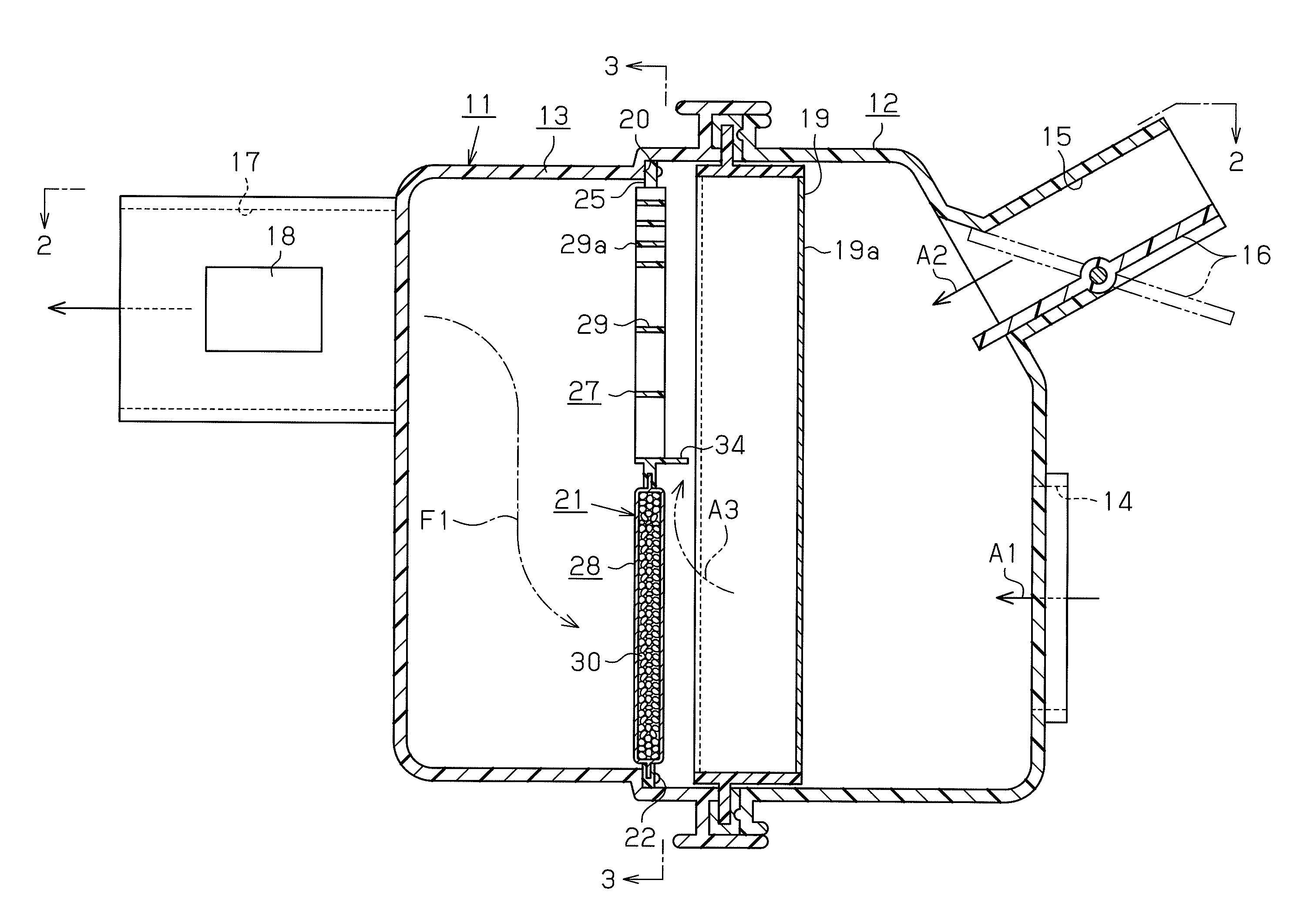
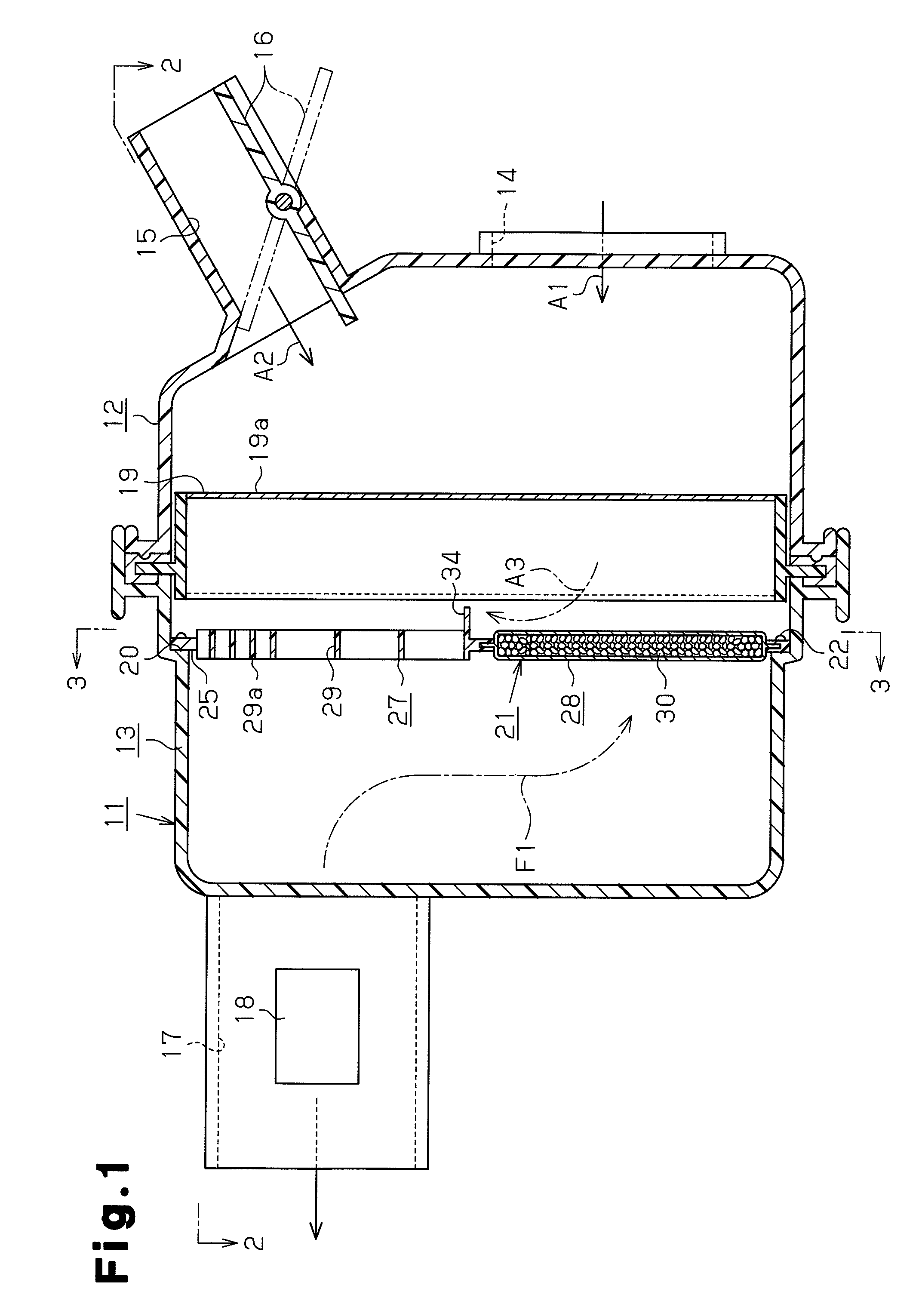
[0025]As shown in FIGS. 1 and 2, a housing 11 of an air cleaner according to the present embodiment includes a first housing portion 12 and a second housing portion 13. The first housing portion 12 and the second housing portion 13 are joined at their openings, and detachably coupled to each other with clamps (not shown).

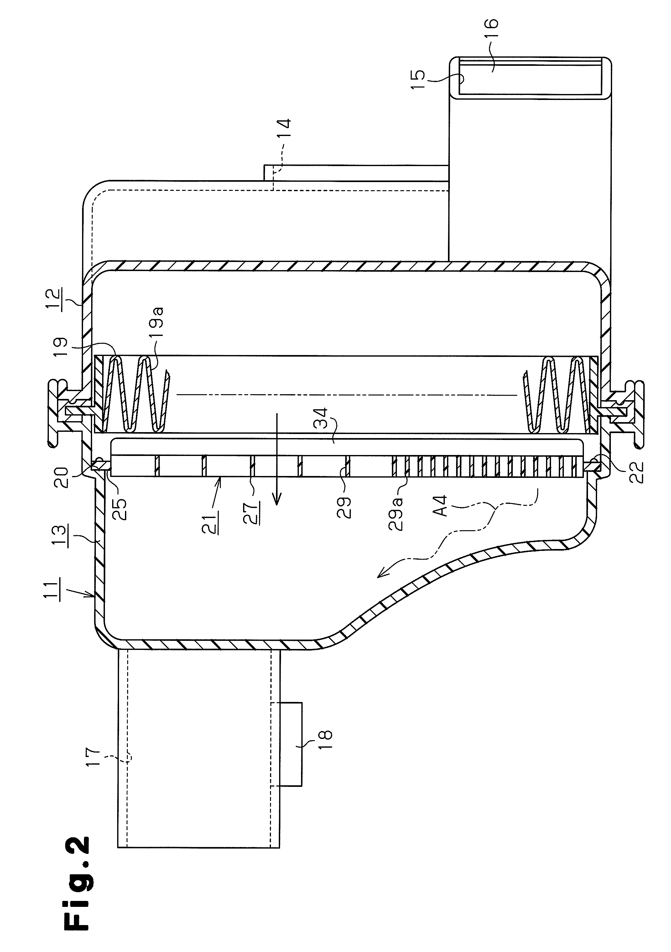
[0026]The first housing portion 12 has air inlet portions, which are a first air inlet port 14 and a second air inlet port 15 in this embodiment. Switching means, which is an on-off valve 16 in this embodiment, is provided at the second air inlet port 15. In a high speed operation of the internal combustion engine, the on-off valve 16 is switched to an open position as illustrated by solid lines in FIG. 1. In other words, the on-off valve 16 is switched to an air introducing position, and air is guided into the housing through both of the first air inlet port 14 and the second air inlet po...

second embodiment

[0050]A second embodiment of the present invention will now be described with reference to FIGS. 6(a), 6(b) and 7. The differences from the first embodiment will mainly be discussed.

[0051]In this embodiment, a portion of the outer frame 25 in the fuel adsorption filter 21 that constructs the open portion 27, and the flow straightening plate 29 including the high-performance portion 29a are omitted. Therefore, the size of the filter according to the second embodiment is half the size of the fuel adsorption filter 21 of the first embodiment.

[0052]The element 19a of the air filter 19 has a synthetic resin retaining member 35 for retaining the shape of the pleats. The retaining member 35 slightly projects toward the fuel adsorption filter 21. The weir 34 is constructed in such a manner that the distal edge is contactable with the distal end of the retaining member 35. The contactable state includes a state in which the parts are always contact each other.

[0053]Thus, the second embodimen...

third embodiment

[0057]A third embodiment of the present invention will now be described with reference to FIG. 8. The differences from the first embodiment will mainly be discussed.

[0058]In the third embodiment, the flow straightening plate 29 having the high-performance portion 29a in the open portion 27 in the fuel adsorption filter 21 is not formed like a lattice, but formed only by fins, which extend parallel in the vertical direction.

[0059]Thus, the third embodiment has substantially the same advantages as the first embodiment.


PUM

PropertyMeasurementUnit
adsorptionaaaaaaaaaa
areaaaaaaaaaaa
flow resistanceaaaaaaaaaa

Abstract

A housing of an air cleaner has an air inlet port and an air outlet port, and incorporates an air filter. In the housing, a fuel adsorption filter is arranged downstream of the air filter in such manner as to intersect an air passage. An open portion and a sheet-like adsorption portion are vertically defined in an outer frame of the fuel adsorption filter. The adsorption portion has a fuel adsorbing function. A weir is provided in a boundary between the open portion and the adsorption portion. The weir limits air flow from the upstream side of the adsorption portion to the upstream side of the open portion. A flow straightening plate having a flow straightening function is provided in the open portion.

Description

BACKGROUND OF THE INVENTION[0001]The present invention relates to a fuel adsorption filter for adsorbing fuel vapor leaking from the intake system of an internal combustion engine such as an automobile engine, and to an air cleaner having the fuel adsorption filter.[0002]Conventionally, for example, Japanese Laid-Open Patent Publication Nos. 2003-42017 and 2003-120445 each disclose an air filter having this type of fuel adsorption filter.[0003]In the configuration disclosed in Japanese Laid-Open Patent Publication No. 2003-42017, an air filter is incorporated in a housing having an air inlet and an air outlet. The air filter traps dust in intake air supplied to the intake system of an internal combustion engine. In the housing, a sheet-like fuel adsorption filter having a fuel adsorbent such as activated carbon is located downstream of the air filter. The fuel adsorption filter is arranged orthogonal to the passage of air. The fuel adsorption filter adsorbs fuel vapor leaking from t...

Claims


Application Information

Patent Timeline
Patent Type & Authority Patents(United States)
IPC IPC(8): B01D53/02
CPCB01D46/0036B01D46/10B01D53/0407F02M35/10013F02M25/08F02M33/04F02M35/024B01D2253/102F02M35/02B01D2259/4516
Inventor YOSHIDA, TOMOHIROOYAMA, TATSUYASAITO, HARUHIKOOHBA, TOHRUKAMIYA, SHINICHIAIHARA, MASAKIISHIHARA, YOICHI
Owner TOYOTA BOSHOKU KK
Why Eureka
Try Eureka