Exhaust gas system

a gas system and exhaust gas technology, applied in the direction of mechanical equipment, functional valve types, machines/engines, etc., can solve the problems of inability to achieve muffling effect, inability to reduce power of internal combustion engines,

Inactive Publication Date: 2005-09-06
EBERSPACHER EXHAUST TECH GMBH & CO KG
View PDF23 Cites 48 Cited by
  • Summary
  • Abstract
  • Description
  • Claims
  • Application Information

AI Technical Summary

Benefits of technology

[0006]The object of the present invention is to disclose an improved embodiment of an exhaust gas system of the initially described type which, in particular, provides a sufficient muffling effect and simultaneously allows a power increase of the internal combustion engine.
[0008]In an exhaust gas system with two mufflers, through which the exhaust gas is able to flow in a parallel fashion, the present invention proposes that the two mufflers are realized differently with respect to their muffling effect and / or flow resistance, and that a switching unit is provided that makes it possible to selectively activate only or almost exclusively the first muffler or only or almost exclusively the second muffler or both mufflers. A corresponding actuation of the switching unit consequently makes it possible to select between different muffling effects and / or between different flow resistances and—in dependence thereon—between different powers of the internal combustion engine. The invention utilizes the fact that the internal combustion engine, in particular, of a motor vehicle is usually not permanently operated at maximum power. To the contrary, only a low power is required in numerous operating phases. For example, the power of the internal combustion engine is only of minor importance in the idling mode of the internal combustion engine. The exhaust gas system according to the invention makes it possible to provide an improved muffling effect for operating phases, in which a power drop of the internal combustion engine can be accepted, as well as to lower the exhaust gas back-pressure for operating phases, in which the power of the internal combustion engine should be largely uninhibited. In the latter-mentioned instance, the associated decrease in the muffling effect is acceptable or even desirable, for example, in order to produce an acoustic feedback of the increased power in the form of a “sports car sound.”
[0009]According to one advantageous additional development, the first muffler is designed in such a way that an optimized muffling effect is achieved, in particular, for lower frequencies. The second muffler is designed in such a way that an optimized power of the internal combustion engine is achieved. This design of the mufflers makes it possible to realize an optimal muffling effect at a low power requirement of the internal combustion engine and to lower the exhaust gas back-pressure at a higher power requirement.
[0011]In one advantageous additional development, the control device is able to actuate the switching unit in such a way that the exhaust gas only or predominantly flows through the first muffler in a lower speed range, that the exhaust gas only or predominantly flows through the second muffler in the medium speed range, and that the exhaust gas flows through both mufflers in a parallel fashion in an upper speed range. This embodiment of the exhaust gas system can be very easily realized in such a way that it is optimized with respect to the muffling effect for smaller exhaust gas volume flows and with respect to the power of the internal combustion engine for medium exhaust gas volume flows. Both mufflers are active for higher volume flows in order to lower the total flow resistance of the exhaust gas system.

Problems solved by technology

However, the power of the internal combustion engine undesirably decreases as the exhaust gas back pressure increases.
In the design of mufflers, the attainable muffling effect consequently is limited by the associated power drop of the internal combustion engine.

Method used


Image

  • Exhaust gas system
  • Exhaust gas system

Examples


Embodiment Construction

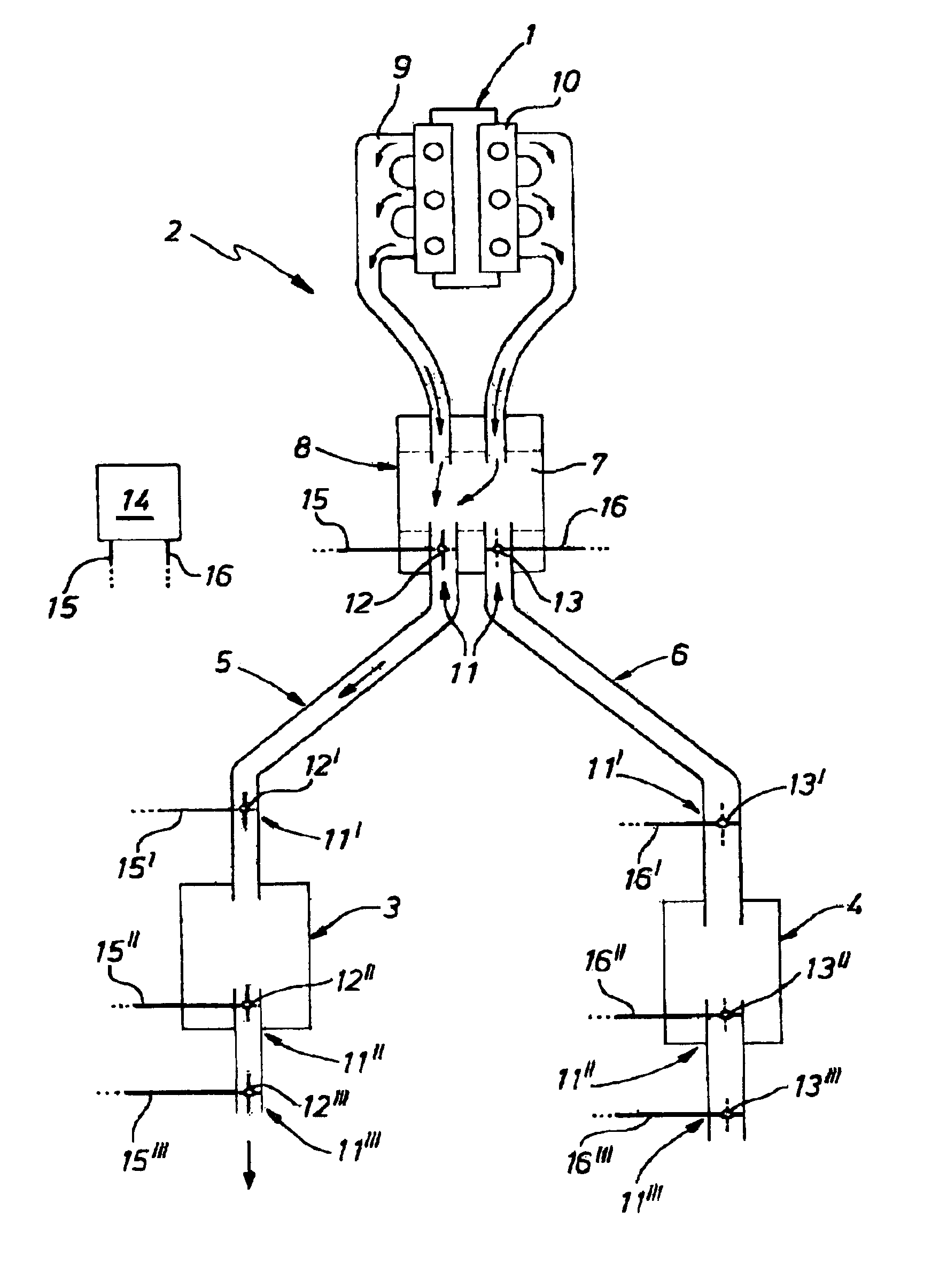
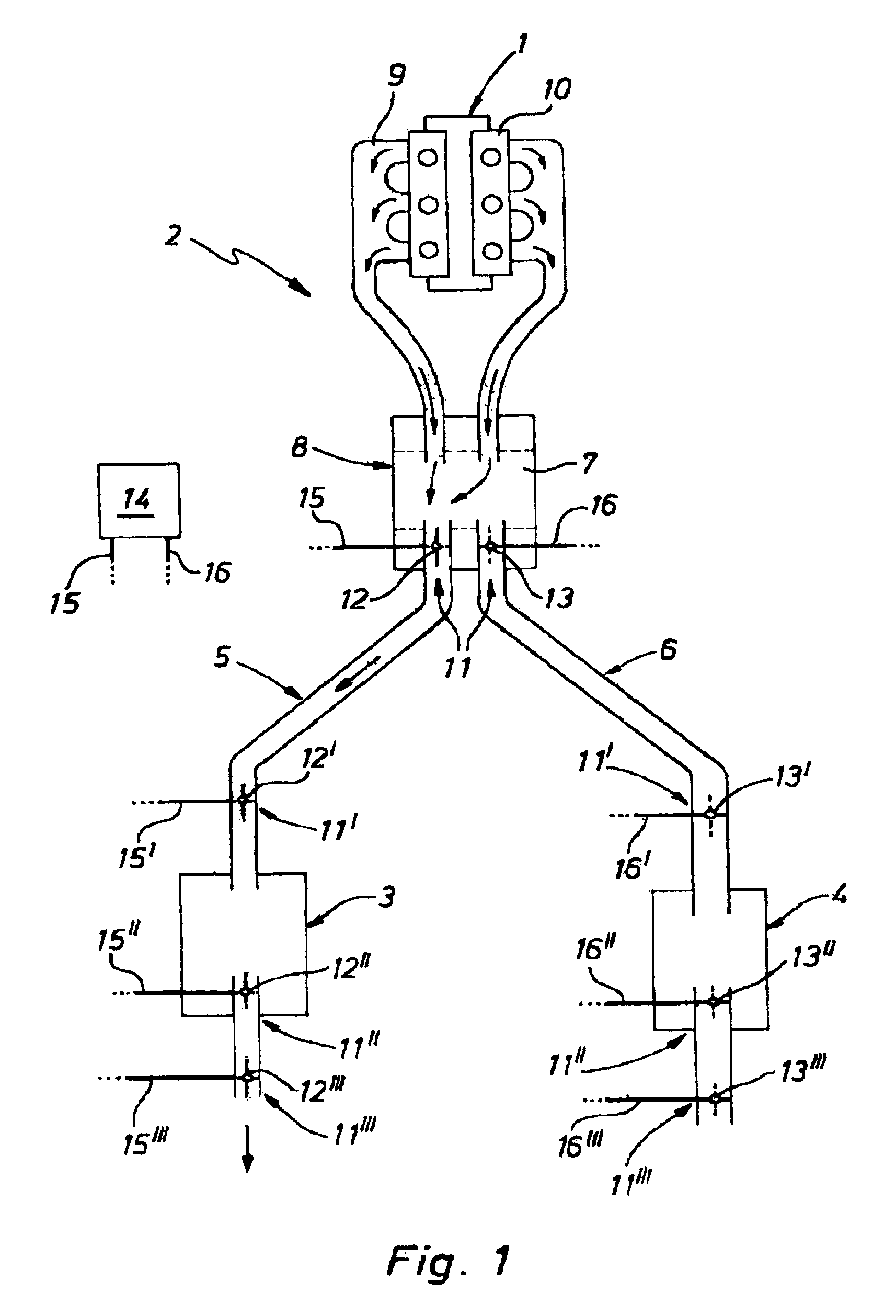
[0016]According to FIG. 1, an internal combustion engine 1, in particular, of a motor vehicle is equipped with an exhaust gas system 2 according to the invention. This exhaust gas system 2 comprises at least two mufflers, through which the exhaust gas is able to flow in a parallel fashion, namely a first muffler 3 and a second muffler 4 that, for example, are realized in the form of rear mufflers. It would, in principle, be possible to arrange both mufflers 3, 4 in one common exhaust gas pipe assembly in such a way that the exhaust gas is able to flow through both mufflers in a parallel fashion. However, in the preferred embodiment shown, the exhaust gas system 2 comprises two parallel exhaust gas pipe assemblies, namely a first exhaust gas pipe assembly 5 and a second exhaust gas pipe assembly 6, wherein one of the mufflers 3, 4 is respectively arranged in each exhaust gas pipe assembly. In this context, it is important that the two exhaust gas pipe assemblies 5, 6 are connected to...


PUM


Abstract

An exhaust gas system for an internal combustion engine, in particular, of a motor vehicle has two mufflers through which the exhaust gas is able to flow in a parallel fashion. A switching unit makes it possible to selectively convey the exhaust gas flow of the internal combustion engine only or almost exclusively through the first muffler, or only or almost exclusively through the second muffler, or through both mufflers in a parallel fashion. The two mufflers are realized differently with respect to their muffling effect and / or flow resistance.

Description

CROSS-REFERENCES TO RELATED APPLICATIONS[0001]Not applicable.STATEMENT REGARDING FEDERALLY SPONSORED RESEARCH OR DEVELOPMENT[0002]Not applicable.BACKGROUND OF THE INVENTION[0003]The present invention pertains to an exhaust gas system for an internal combustion engine, in particular, of a motor vehicle.[0004]The combustion gases produced during operation of an internal combustion engine are conveyed from the cylinder head of the internal combustion engine into an exhaust gas pipe assembly that discharges the exhaust gases into the surroundings by means of exhaust manifolds. The inlet of the exhaust gas pipe assembly may also contain an exhaust gas accumulator for each cylinder bank of the internal combustion engine, wherein the manifold pipes lead into this exhaust gas accumulator, and wherein the exhaust gas accumulator introduces the thusly combined exhaust gas flow of the individual cylinders into the exhaust gas pipe assembly. Devices for conditioning and / or cleaning the exhaust ...

Claims


Application Information

Patent Timeline
Patent Type & Authority Patents(United States)
IPC IPC(8): F01N7/02F01N7/00F01N1/16F01N7/04F01N13/02F01N13/04
CPCF01N1/166F01N13/02F01N13/011F01N13/107
Inventor WORNER, SIEGFRIEDSIGEL, ULRICH
Owner EBERSPACHER EXHAUST TECH GMBH & CO KG
Why Eureka
Try Eureka