Cooling water circuit system

a circuit system and cooling water technology, applied in mechanical equipment, transportation and packaging, machines/engines, etc., can solve the problem of high cost of heating equipment production

Inactive Publication Date: 2000-07-04
DENSO CORP
View PDF6 Cites 46 Cited by
  • Summary
  • Abstract
  • Description
  • Claims
  • Application Information

AI Technical Summary

Benefits of technology

According to the present invention, in a cooling water circuit system, cooling water pumped by a first water pump which is driven by a water-cooled engine is circulated in a cooling water circuit, so that cooling water flows through a radiator and a heater core in parallel. An electrically-driven second water pump is disposed in the cooling water circuit at a position where cooling water to be supplied from the first water pump to the radiator and cooling water to be supplied from the first water pump to the heater core flow together. Further, a check valve is disposed in the cooling water circuit in parallel with the second water pump in such a manner that cooling water flows in one way from a water suction side of the second water pump toward a water discharge side of the second water pump. Thus, when the second water pump is operated, a total amount of cooling water pumped by the first water pump and cooling water pumped by the second water pump can be introduced into the radiator and the heater core. As a result, the cooling water circuit system can improve heating effect for a passenger compartment in the winter while improving engine-cooling effect in the summer.
Further, the check valve prevents cooling water only circulates between the water suction side of the second water is pump and the water discharge side of the second water pump. On the other hand, when the second water pump is stopped, the check valve is opened so that cooling water bypasses the second water pump. Thus, flow resistance in the cooling water circuit can be reduced when the second water pump is stopped. As a result, both the heating effect and cooling effect can be improved in the cooling water circuit system with a simple structure.
More preferably, during a heating mode when the engine is in idling, the second water pump is operated when the temperature of the cooling water is lower than a predetermined temperature. Therefore, even when the engine is in idling so that cooling water circulated by the first water pump is decreased, a total amount of cooling water flowing into the heater core can be increased because the second water pump is operated. Thus, even in the engine-idling, heating capacity of the heater core for the passenger compartment can be improved.
Preferably, during a cooling mode when the engine is in idling, the second water pump is operated when the temperature of cooling water is higher than a predetermined temperature. When the engine is in idling, a rotation speed of the engine is decreased, and amount of cooling water circulated by the first water pump is decreased. However, because the second water pump is operated, the amount of cooling water flowing into the radiator can be increased, and the engine-cooling capacity can be improved.

Problems solved by technology

However, in the conventional heating apparatus, because flow resistance of cooling water in the cooling water circuit becomes larger by providing the heat accumulating tank, it is necessary to operate the water pump with a high power.
Further, because the cooling water circuit of the heating apparatus becomes complex by the heat accumulating tank, the valve for switching cooling water flow and a control circuit of the valve are also necessary, and the heating apparatus is produced in high cost.

Method used


Image

  • Cooling water circuit system
  • Cooling water circuit system
  • Cooling water circuit system

Examples


Embodiment Construction

Preferred embodiments of the present invention are described hereinafter with reference to the accompanying drawings.

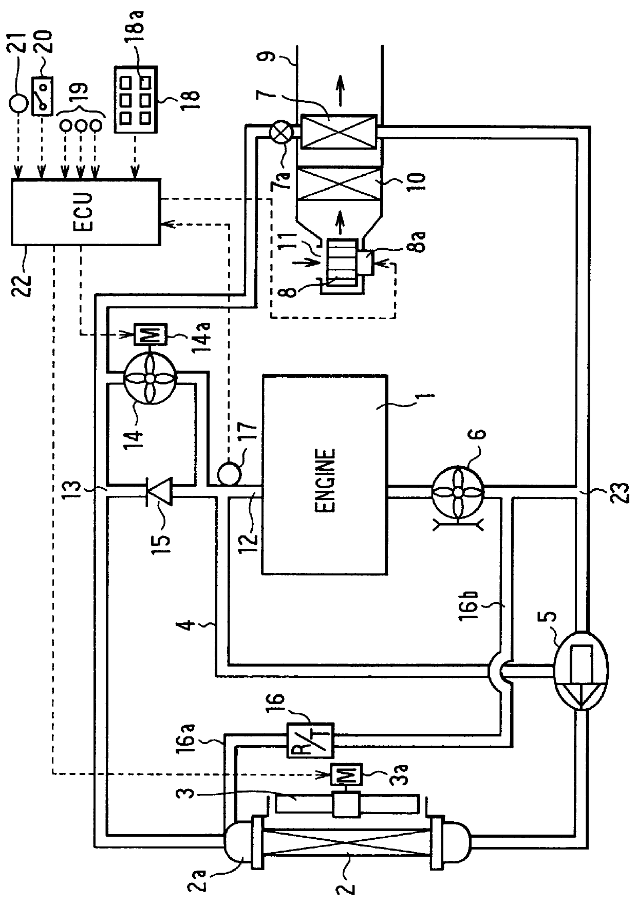
A first preferred embodiment of the present invention will be now described with reference to FIGS. 1-4D. In the first embodiment, the present invention is typically applied to a hybrid vehicle using an engine and a motor as a driving source for running the vehicle. As shown in FIG. 1, in a cooling water circuit system of the first embodiment, a water-cooled engine (hereinafter referred to as "engine") 1 for running the vehicle is disposed in a cooling water circuit. A radiator 2 is disposed in the cooling water circuit to perform heat exchange between engine-cooling water (hot water) from the engine 1 and outside air blown by a cooling fan 3, so that engine-cooling water (hereinafter referred to as "cooling water") is cooled in the radiator 2 by outside air (i.e., air outside a passenger compartment). The cooling fan 3 is an axial flow fan driven electrically by a mo...


PUM


Abstract

In a cooling water circuit system, cooling water pumped by a mechanically-driven first water pump circulates in a cooling water circuit, and flows through a radiator and a heater core in parallel in the cooling water circuit. An electrically-driven second water pump is disposed in the cooling water circuit at a position where cooling water to be supplied to the radiator from the first water pump and cooling water to be supplied to the heater core from the first water pump flow together. A check valve is provided in the cooling water circuit in parallel with the second water pump so that cooling water flows in one way from a water suction side of the second water pump toward a discharge side thereof. Thus, when the second water pump is operated, a total amount of cooling water pumped by the first water pump and the second water pump can flow through the radiator and the heater core. As a result, the cooling water circuit system can improve engine-cooling effect in the summer, while improving heating effect of a passenger compartment in the summer.

Description

This application is related to and claims priority from Japanese Patent Application No. Hei. 10-113835 filed on Apr. 23, 1998, the contents of which are hereby incorporated by reference.1. Field of the InventionThe present invention relates to a cooling water circuit system which improves cooling effect for cooling water-cooled engine mounted on a vehicle in the summer while improving heating effect of a passenger compartment of the vehicle in the winter.2. Description of Related ArtIn a conventional heating apparatus described in JP-A-9-272327 by the applicant of the present invention, a heater core, a heat accumulating tank and an electrically-driven water pump are provided in a cooling water circuit, and a valve is provided to control amounts of cooling water flowing into a water-cooled engine, the heater core and the heat accumulating tank. When a heating mode is set when the engine is stopped, the electrically-driven water pump and the valve are operated so that cooling water c...

Claims


Application Information

Patent Timeline
Patent Type & Authority Patents(United States)
IPC IPC(8): B60H1/04B60H1/02B60H1/12F01P5/00F01P5/10F01P7/00F01P7/08F01P7/16F01P7/14F01P5/12
CPCB60H1/02B60H1/12F01P5/10F01P7/08F01P7/162F01P2005/105F01P2005/125F01P2023/08F01P2025/32F01P2050/24F01P2060/08
Inventor MORIKAWA, TOSHIOINOUE, YOSHIMITSUITO, HAJIMESUGI, HIKARU
Owner DENSO CORP
Why Eureka
Try Eureka