Refrigeration/air conditioning equipment

a technology of refrigeration/air conditioning equipment and equipment, which is applied in the direction of refrigeration components, mechanical equipment, light and heating equipment, etc., can solve the problems of unstable operation, low efficiency, and insufficient heating capacity of conventional refrigeration/air conditioning equipment, so as to increase the efficiency of defrosting operation and increase the heating capacity. , the effect of sufficient heating capacity

Active Publication Date: 2006-04-20
MITSUBISHI ELECTRIC CORP
View PDF13 Cites 89 Cited by
  • Summary
  • Abstract
  • Description
  • Claims
  • Application Information

AI Technical Summary

Benefits of technology

[0011] In view of these problems, it is an object of the present invention to provide refrigeration / air conditioning equipment that has a higher heating capacity than conventional gas injection cycles, and exhibits a sufficient heating capacity even in a cold district where the outdoor temperature is −10° C. or lower, and also to increase the efficiency during the defrosting operation.
[0027] Thus, even when a high flow rate of the gas refrigerant is injected, sufficient heating capacity can be provided even under such a condition as the heating capacity tends to decrease owing to low outdoor temperature or the like, by preventing the reduction in the discharge temperature of the compressor and allowing the indoor heat exchanger to exhibit sufficient heat-exchange performance. According to the present invention, the gas refrigerant to be injected is supplied not from the gas-liquid separator but through the gasification of the bypassed refrigerant with the second internal heat exchanger. Thus, the variation in the fluid volume caused by the gas-liquid separator can be avoided. Thus, more stable operation can be achieved. In addition, the gas injection can be increased while the reduction in the discharge temperature of the compressor is prevented. Thus, the heating capacity is further increased, and the efficiency during the defrosting operation is improved.

Problems solved by technology

However, these pieces of conventional refrigeration / air conditioning equipment have the following problems.
This variation causes fluctuations in the distribution of a liquid refrigerant level in a refrigeration cycle and makes the operation unstable.
Conversely, when the flow rate of the refrigerant to be injected increases and the gas refrigerant becomes deficient, the liquid refrigerant is also injected into the compressor.
Thus, the injection flow rate hardly balances with the flow rate of the gas refrigerant flowing into the gas-liquid separator.
This variation often causes fluctuations in the distribution of the refrigerant in the refrigeration cycle, making the operation unstable.
Furthermore, the heater as in the Japanese Unexamined Patent Application Publication No. 2001-263882 is only used in a defrosting operation and does not contribute significantly to the increase in the capacity during a heating operation.

Method used


Image

  • Refrigeration/air conditioning equipment
  • Refrigeration/air conditioning equipment
  • Refrigeration/air conditioning equipment

Examples


embodiment 1

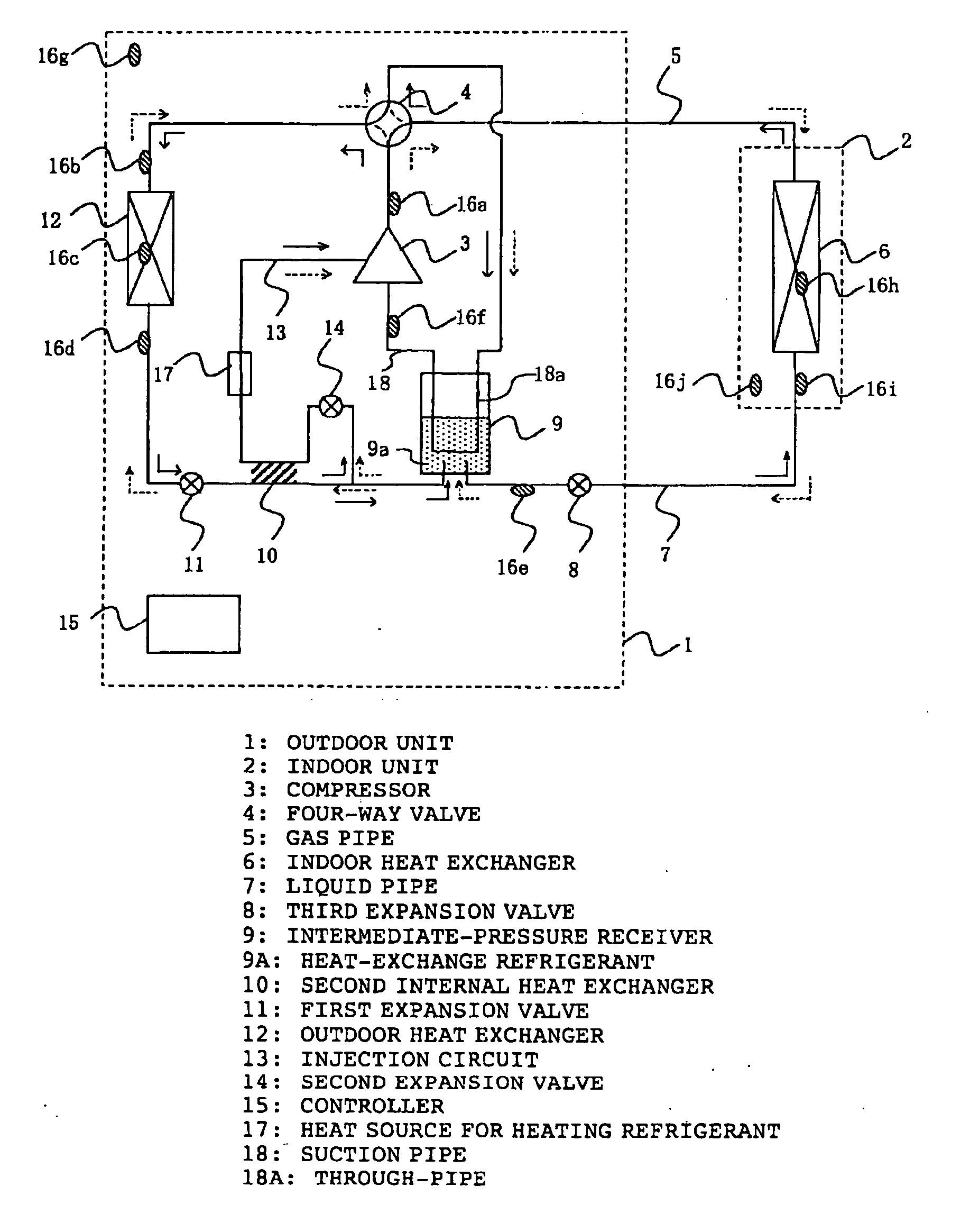
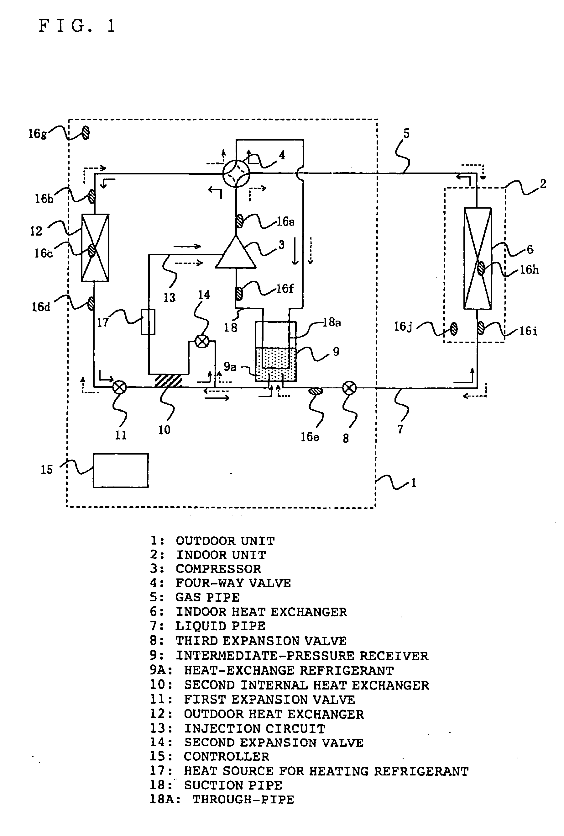
[0040]FIG. 1 is a refrigerant circuit diagram of refrigeration / air conditioning equipment of Embodiment 1 according to the present invention. In FIG. 1, an outdoor unit 1 includes a compressor 3, a four-way valve 4 for switching between heating and cooling, an outdoor heat exchanger 12, a first expansion valve 11 serving as a first decompressor, a second internal heat exchanger 10, a third expansion valve 8 serving as a third decompressor, an injection circuit 13, a second expansion valve 14 serving as a second decompressor, an intermediate-pressure receiver 9, and a heat source 17 for heating a refrigerant. A suction pipe 18 of the compressor 3 passes through the intermediate-pressure receiver 9. Thus, a refrigerant in this through-pipe 18a of the suction pipe 18 can exchange heat with a refrigerant 9a in the intermediate-pressure receiver 9. The heat source 17 heats a refrigerant circulating through the injection circuit 13.

[0041] The capacity of the compressor 3 can be controlle...


PUM


Abstract

Refrigeration / air conditioning equipment includes a first internal heat exchanger for exchanging heat between a refrigerant to be sucked in a compressor and a high-pressure liquid refrigerant, an injection circuit for evaporating a bypassed high-pressure liquid at intermediate pressure and injecting the vaporized refrigerant into the compressor, a second internal heat exchanger for exchanging heat between the high-pressure liquid refrigerant and the refrigerant to be injected, and a heat source for heating the refrigerant to be injected.

Description

BACKGROUND OF THE INVENTION [0001] 1. Field of the Invention [0002] The present invention relates to refrigeration / air conditioning equipment, and particularly to refrigeration / air conditioning equipment in which the heating capacity at low outdoor temperature is improved by gas injection, and a defrosting operation is performed efficiently. [0003] 2. Description of the Related Art [0004] Japanese Unexamined Patent Application Publication No. 2001-304714 discloses refrigeration / air conditioning equipment including a gas-liquid separator in an intermediate-pressure portion between a condenser and an evaporator. A gas refrigerant separated by the gas-liquid separator is injected into an intermediate-pressure portion of a compressor to increase the heating capacity. [0005] Japanese Unexamined Patent Application Publication No. 2000-274859 discloses another conventional refrigeration / air conditioning equipment without a gas-liquid separator. In this equipment, part of a high-pressure li...

Claims


Application Information

Patent Timeline
Patent Type & Authority Applications(United States)
IPC IPC(8): F25B13/00F25B41/00
CPCF25B1/10F25B13/00F25B40/00F25B2313/008F25B2341/0653F25B2341/066F25B2400/053F25B2400/054F25B2400/13F25B2400/16F25B2600/0271F25B2600/2509F25B2600/2513F25B2700/21151F25B2700/21152F25B2700/2117Y02B30/72F25B2500/31F25B41/35F25B41/385F25B41/39Y02B30/70
Inventor AOKI, MASANORIYOSOMIYA, MASATOUNEZAKI, FUMITAKESAITOU, MAKOTOSAIKUSA, TETSUJI
Owner MITSUBISHI ELECTRIC CORP
Why Eureka
Try Eureka