Ceramic wall-flow filter including heat absorbing elements and methods of manufacturing same

a ceramic wall-flow filter and filter technology, which is applied in the field of ceramic wall-flow filters, can solve the problems of higher maximum temperatures, fuel penalty, pressure drop in gas, etc., and achieve the effect of increasing the bulk heat capacity of the filter, and reducing the amount of was

Active Publication Date: 2006-08-31
CORNING INC
View PDF15 Cites 40 Cited by
  • Summary
  • Abstract
  • Description
  • Claims
  • Application Information

AI Technical Summary

Benefits of technology

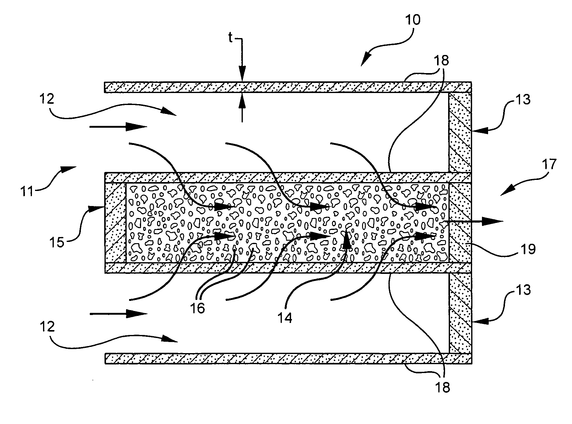
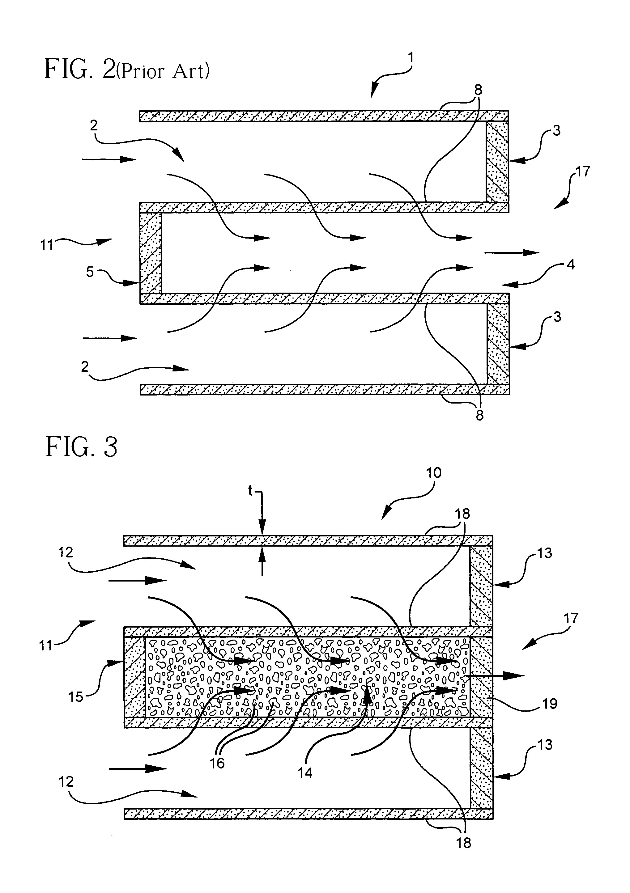
[0011] These and other advantages are attained by a ceramic wall-flow filter having utility for filtering particulate matter from gases in accordance with the present invention. According to embodiments of the invention, the ceramic wall-flow filter includes a filter body having an array of porous ceramic walls defining a pattern of inlet and outlet cells traversing the body and extending between an inlet end and an outlet end, the inlet cells including first plugs at the outlet end, and the outlet cells including second plugs at the inlet end, and heat absorbing elements disposed within at least some of said outlet cells such that a bulk heat capacity of the elements in the outlet cells is greater than a bulk heat capacity of the elements in inlet cells, if any are provided in such inlet cells. Most preferably, heat absorbing elements are provided only in the outlet cells. The presence of the heat absorbing elements increases a bulk heat capacity of the filter without substantially interfering with a flow of gas through the porous ceramic walls. In particular, according to one advantage, the wall thickness may be made smaller as compared to prior art structures while the addition of the elements maintains at least an equivalent level of bulk heat capacity. Optionally, of course, the wall thickness may be made the same with an increase in bulk heat capacity as compared to the prior art.
[0012] In accordance with one embodiment, the elements disposed within the cells are a porous ceramic foam material. In this regard, the ceramic forming the foam may be the same ceramic material that forms the porous ceramic walls. The ceramic foam may be applied, for example, to coat the inner surfaces of the outlet cells and / or to fill the interior of the outlet cells. Alternatively or additionally, the ceramic foam may be applied to coat the inner surfaces of at least some of the inlet cells. However, if done, such coating must be applied to a lesser extent than in the outlet cells thereby resulting in higher bulk heat capacity in the outlet cells than inlet cells while retaining suitable soot and ash storage capacity. Most preferably, the permeability of the ceramic foam material is higher than the permeability of the ceramic material forming the walls, and may be implemented as a cellular structured foam, such as an open cell foam. The foam may be attached to the inner surfaces of the cell walls, for example, by fusion. Alternatively, the heat absorbing, gas conductive elements may comprise loose material and be unattached to the inner surfaces of the cells. Additional plugs may be employed to retain the loose material in the cells.
[0013] In still another embodiment, the heat absorbing elements disposed within at least some of the outlet cells may be implemented as webs of ceramic material. In this regard, the webs may be implemented to extend completely across the outlet cells, for example, or be integrally connected to the inner surface of the outlet cell. The ceramic wall-flow filter may be implemented such that the interior of the outlet cells have a square cross section, and the web connects across two corners of the interior in a diagonal configuration. Alternatively, two webs may be connected across different opposing corners of the interior in an x-shaped configuration. In yet another embodiment, two webs may be implemented to connected opposing midpoints of the walls in a cross-shaped configuration. Alternatively, the thickness of the webs may be different from the thickness of the porous walls defining the inlet and outlet cells.
[0014] According to yet a further aspect of the invention, a method of manufacturing a ceramic wall flow filter is provided comprising the steps of forming ceramic material, preferably by extrusion, into a filter body having an array of porous ceramic walls defining a pattern of inlet and outlet cells traversing the body and extending between an inlet end and an outlet end, plugging the inlet cells with first plugs at the outlet end, plugging the outlet cells with second plugs at the inlet end, and during the step of extruding or thereafter, forming heat absorbing elements within at least some of the outlet cells such that a bulk heat capacity of the outlet cells is greater than a bulk heat capacity of the inlet cells. Preferably, the heat absorbing elements are only formed in the outlet cells.
[0015] These and other advantages and features of the present invention will become more apparent from the following detailed description of the preferred embodiments of the present invention when viewed in conjunction with the accompanying drawings. Where appropriate, identical features have been identically numbered.

Problems solved by technology

The application of such a filter in the exhaust gas stream causes a pressure drop in the gas that is filtered therethrough.
Thus, presence of the filter results in a fuel penalty since additional work must be done by the engine to push the exhaust gas through the filter.
A disadvantage with this approach is that, for a given soot loading level, a regeneration event will result in higher maximum temperatures for a filter with thin walls.
This can result in damage to the filter, including catalyst deactivation, or cracking, or even melting of the filter.
These particulates decrease the effective diameter of the cells and further contribute to the pressure drop across the filter, thereby increasing the back pressure that acts against the engine exhaust.
During an uncontrolled regeneration, the combustion of the soot may produce temperature spikes within the filter which can thermally shock and crack, or even melt, the filter.
Correspondingly, whereas reduction in the wall thickness of the cells can reduce back pressure, this solution is not optimal in view of the fact that the durability is reduced as a result.
Further, whereas increased wall thickness of the cells is desirable to increase the durability of the filter, such increased wall thickness also undesirably increases the backpressure.

Method used


Image

  • Ceramic wall-flow filter including heat absorbing elements and methods of manufacturing same
  • Ceramic wall-flow filter including heat absorbing elements and methods of manufacturing same
  • Ceramic wall-flow filter including heat absorbing elements and methods of manufacturing same

Examples


Embodiment Construction

[0033]FIG. 1A illustrates a partially-sectioned isometric view of a prior art ceramic wall-flow filter 1, and FIG. 1B shows an enlarged outlet end partial view of the prior art honeycomb structure for the filter 1. As illustrated in FIGS. 1A, 1B, the conventional filter 1 has an end-plugged honeycomb structure with inlet cells 2 which are plugged in the views shown on the outlet end 17, and outlet cells 4 that are open at the outlet end. The plurality of cells extend between an inlet 11 and an outlet 17 ends of the filter 1 and have generally square cross-sections formed by interior porous walls 8 that run substantially longitudinally between the inlet 11 and outlet 17 ends of the filter 1. The cells 2, 4 are arranged to alternate between inlet cells 2 and outlet cells 4, and plugged in an alternating manner for each end, resulting in a checkered pattern of alternating cells. Therefore, inlet cells 2 are bordered on all sides by outlet cells 4, and vice versa (of course except adjac...


PUM

PropertyMeasurementUnit
temperatureaaaaaaaaaa
thicknessaaaaaaaaaa

Abstract

A ceramic wall-flow filter for filtering particulate matter from gases and methods for manufacturing such wall-flow filters are disclosed. The filter includes an array of porous ceramic walls defining a pattern of end-plugged inlet and outlet cells, and heat absorbing elements disposed within at least some of the outlet cells such that a bulk heat capacity of the outlet cells is greater than a bulk capacity of the inlet cells. The heat absorbing elements increase a bulk heat capacity of the filter without substantially interfering with a flow of gas through the porous ceramic walls by allowing thinner walls. According to the method, during the step of extruding or thereafter, heat absorbing elements are formed within at least some of the outlet cells such that a heat capacity of the outlet cells is greater than the inlet cells.

Description

BACKGROUND OF THE INVENTION [0001] 1. Field of the Invention [0002] The present invention is directed to a filter having a multi-cellular structure. In particular, the present invention is directed to a wall-flow filter for trapping diesel exhaust particulates and methods for manufacturing such filters. [0003] 2. Technical Background [0004] Wall-flow filters are used in the purification of diesel exhaust. Typically, such diesel particulate filters are made of cordierite or silicon carbide and include a honeycomb body having thin interconnecting porous walls which are arranged and configured to form parallel cells longitudinally extending between the end faces of the structure. Alternating cells on one end face of the honeycomb are plugged with a ceramic filler material to form a “checkerboard” pattern. The pattern is reversed on the opposite side so that the ends of each cell are blocked at only one end of the structure. When diesel exhaust gas enters the filter through one end face...

Claims


Application Information

Patent Timeline
Patent Type & Authority Applications(United States)
IPC IPC(8): B01D46/00
CPCB01D39/2093Y10T428/24157B01D46/2444B01D46/2466B01D46/247B01D46/2474B01D46/4218B01D2046/2481B01D2046/2492B01D2046/2496F01N3/0222F01N2240/10F01N2330/06F01N2330/30Y02T10/20Y10S55/05Y10S264/48Y10S55/30Y10S55/10F01N13/009Y10T428/24149B01D46/2429Y02T10/12B01D46/249B01D46/2486B01D46/2498B01D46/24494
Inventor BARDHAN, PRONOBBEALL, DOUGLAS MUNROEMILLER, KENNETH RICHARDWIGHT, JOHN FORREST JR.
Owner CORNING INC
Why Eureka
Try Eureka