New concept high-speed aerocraft propulsion system layout method

A high-speed aircraft and propulsion system technology, applied in the field of propulsion system layout, can solve the problems that the aircraft can provide enough power, cannot start by itself, cannot be reused, etc., and achieve ultra-high heat exchange efficiency, weight reduction, and large heat exchange Effect

Active Publication Date: 2014-10-22
BEIHANG UNIV
View PDF5 Cites 24 Cited by
  • Summary
  • Abstract
  • Description
  • Claims
  • Application Information

AI Technical Summary

Problems solved by technology

[0003] In order to achieve high-speed flight, people first used hydrogen / oxygen rocket engine, which has a high thrust-to-weight ratio and can provide enough power for high-speed aircraft, but its application is limited due to the limitation of its launch method and the shortcomings of being unable to be reused. In a few fields such as aerospace propulsion and missile power; advanced turbojet engines can also provide power for aircraft in the range of flight Mach number 0 to 3, but when flying at higher speeds, their economy is poor and technical costs Too large, and it cannot provide enough power for aircraft operating at higher Mach numbers; ramjets can operate at high flight speeds with relatively good performance, but cannot start themselves at low speeds; turbines base combination engine such as figure 1 It combines the two technologies of turbine engine and ramjet engine, integrates the advantages of turbine engine and ramjet engine in their respective applicable flight ranges, and can be used for regular take-off and landing.
However, due to its high fuel consumption rate when flying at low speeds; when flying at high speeds, the turbine engine does not work and becomes an additional weight, and it needs thermal protection for its appearance, so far only a few practical engineering applications have been obtained.

Method used


Image

  • New concept high-speed aerocraft propulsion system layout method
  • New concept high-speed aerocraft propulsion system layout method
  • New concept high-speed aerocraft propulsion system layout method

Examples


Embodiment Construction

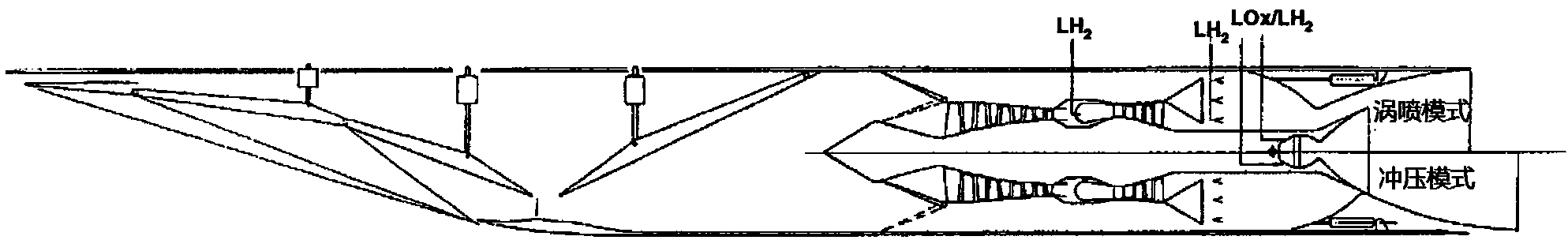
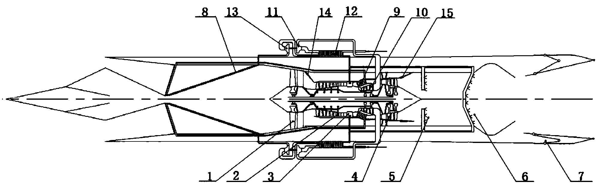
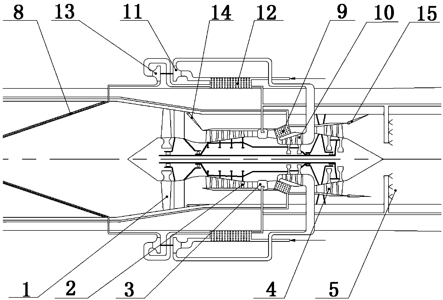
[0031] The present invention is a new-concept high-speed aircraft propulsion system layout based on turbofan-rocket combined engine and supercritical state fluid circulation, including a closed fluid circulation under supercritical state and a mainstream Brayton cycle. It can be used as a high-speed aircraft propulsion system, and its specific implementation is as Figure 4 shown. The Brayton cycle of the system includes: fan 1, core compressor 2, pre-combustion chamber 3, air turbine 4, main combustion chamber 6, air intake 16, tail nozzle 7, and the closed cycle of the system includes: the first heat exchange 8, the second heat exchanger 9, the core turbine 10, the working medium turbine 11, the third heat exchanger 12, the working medium pump 13; in this embodiment, the engine is in Ma=4 state, the afterburner 5, The first valve 14 and the second valve 15 are in a non-working state, so in Figure 4 Not marked in. In the Brayton cycle, the air inlet 16 is located at the f...


PUM


Abstract

The invention provides a new concept high-speed aerocraft propulsion system layout method. Two cycles are built in a propulsion system, namely a Brayton cycle with the air as the working medium and a closed cycle with supercritical state fluid as the working medium. The two cycles are coupled through a supercritical microscopic scale heat exchange technology, a supercritical state fluid turbine and compressor power balance. By adjusting related valves, the propulsion system can be in a turbofan engine model when taking off or flying at a low speed and in a turbine rocket engine model when flying at a high Mach number, so that it is guaranteed that the aerocraft can effectively cruise for a long time in both a subsonic state and a supersonic state. Through the supercritical microscopic scale heat exchange technology, the gas flow temperature at an inlet of a compressor can be effectively reduced when the propulsion system is flying at a high speed, and when the supercritical microscopic scale heat exchange technology is applied in combination with a closed cycle technology, optical distribution of energy of the propulsion system can be achieved. By means of the method, the defects of the propulsion system of an existing high-speed aerocraft are overcome, and working performance of the high-speed aerocraft propulsion system is remarkably improved when Ma ranges from 0 to 5.

Description

technical field [0001] The invention relates to a propulsion system layout method based on turbofan-rocket combined engine and supercritical state fluid circulation, which is mainly used for the propulsion system of high-speed aircraft whose flight Mach number is within the range of 0-5. Background technique [0002] There is an urgent need for high-speed flight in the military and civilian fields, and high-speed aircraft is an important development direction in the future aviation field. In terms of military use, the implementation of global strikes and time-sensitive attacks will inevitably require aircraft with high-speed flight capabilities. In terms of civilian use, supersonic passenger and cargo transportation with good economy will bring great convenience to people's lives. Currently, one of the major problems plaguing high-speed flight is the propulsion system of the aircraft. Although many existing propulsion systems can provide power for high-speed aircraft, they ...

Claims


Application Information

Patent Timeline
Patent Type & Authority Applications(China)
IPC IPC(8): F02K7/16
Inventor 陈懋章邹正平刘火星付超
Owner BEIHANG UNIV
Why Eureka
Try Eureka