
Temperature controlled liquid dispenser, containers therefore, and bag-in-box container construction

a temperature control and dispenser technology, applied in the field of liquid dispensers, can solve the problems of limited amount of cooled or heated water of the desired temperature available, bag does not provide a shape-retaining container, heat conduction properties, etc., and achieves good thermal conductive properties, high heat capacity, effective and efficient transfer of thermal energy

Active Publication Date: 2013-06-11
GROESBECK R CLAY
View PDF48 Cites 40 Cited by
  • Summary
  • Abstract
  • Description
  • Claims
  • Application Information

AI Technical Summary

Benefits of technology

The system enables rapid and efficient cooling or heating of the entire contents of the liquid storage container, maintaining the desired temperature and providing continuous access to cooled or heated liquid without contamination, outperforming traditional methods by utilizing thermal conduction pads and strategically designed bag-in-box containers.

Problems solved by technology

Thus, only a limited amount of cooled or heated water of the desired temperature is available at any time.
However, the bag does not provide a shape retaining container and the box is needed to provide structure and shape to the container.
However, with bag-in-box containers, the cardboard forming the box for the bag-in-box containers generally has poor heat conduction properties so provides relatively poor heat conduction between the bag and the environment outside the box.
The amount of cooled water available at any one time is limited to somewhat less than the capacity of the cooling system reservoir as ambient temperature water is added to the cooled water in the reservoir as the cooled water is dispensed.
This can be a slow process because the cooling has to take place through the box of the bag-in-box container.
Relatively fast cooling of the water is not achieved.

Method used


Image

  • Temperature controlled liquid dispenser, containers therefore, and bag-in-box container construction
  • Temperature controlled liquid dispenser, containers therefore, and bag-in-box container construction
  • Temperature controlled liquid dispenser, containers therefore, and bag-in-box container construction

Examples


Embodiment Construction

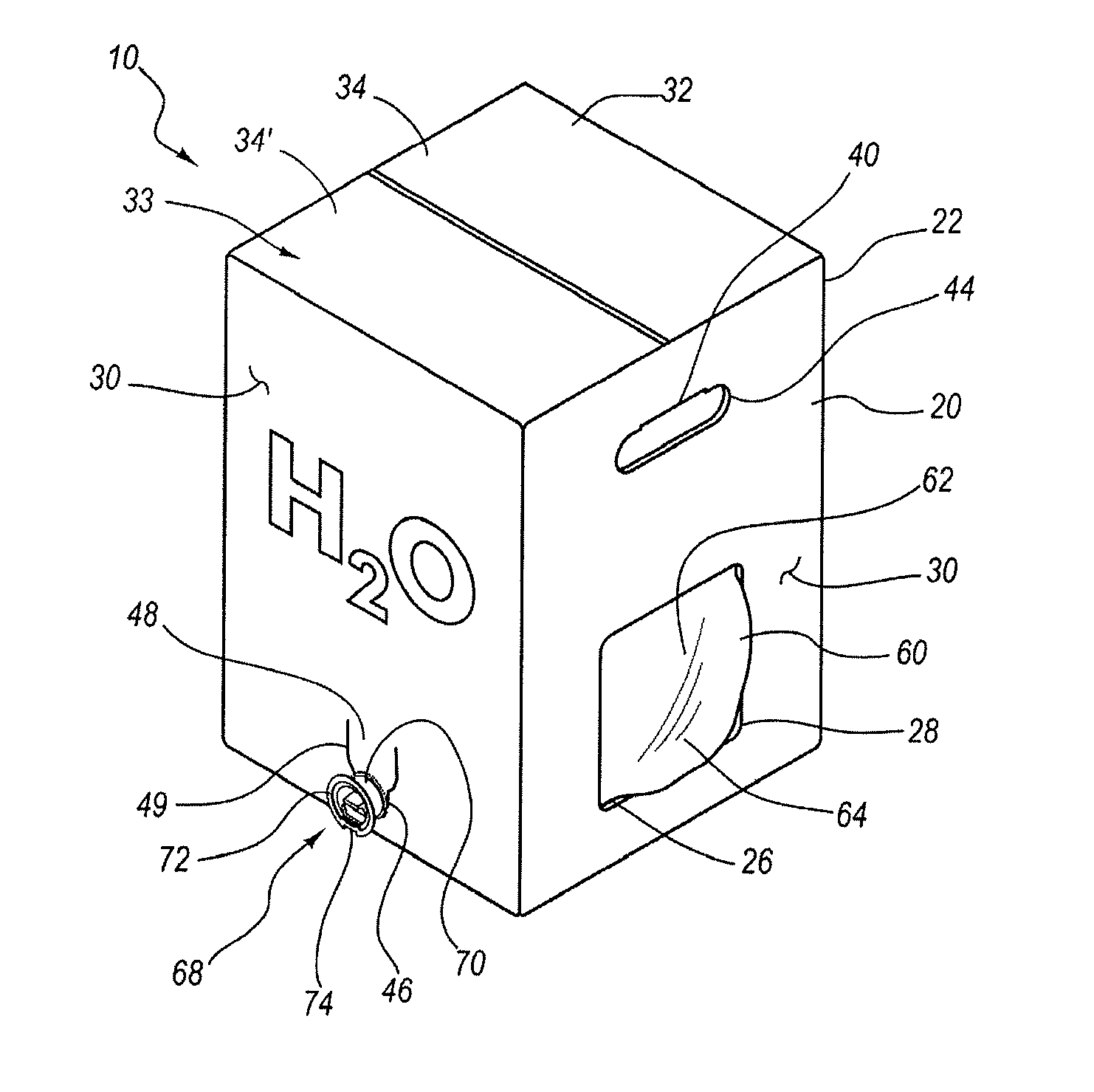
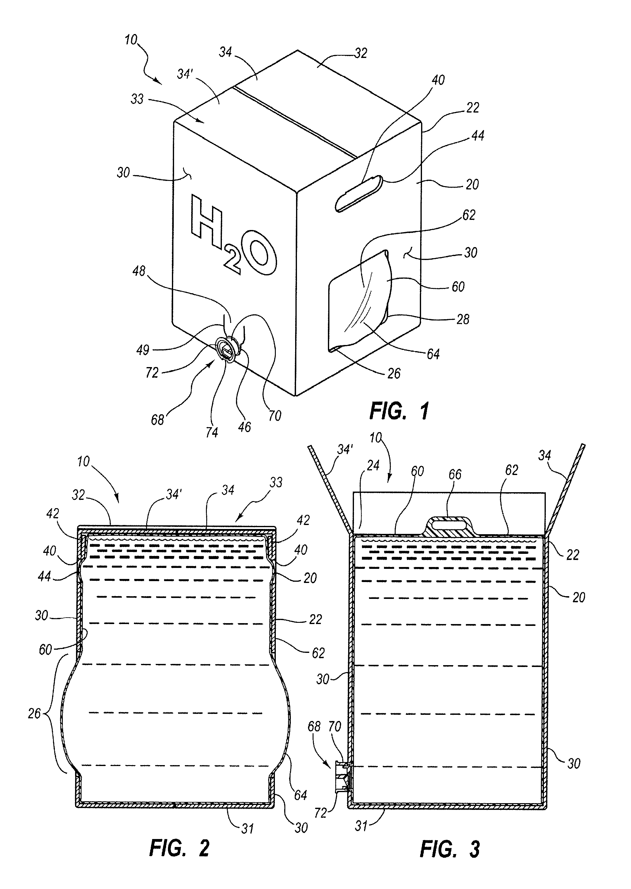
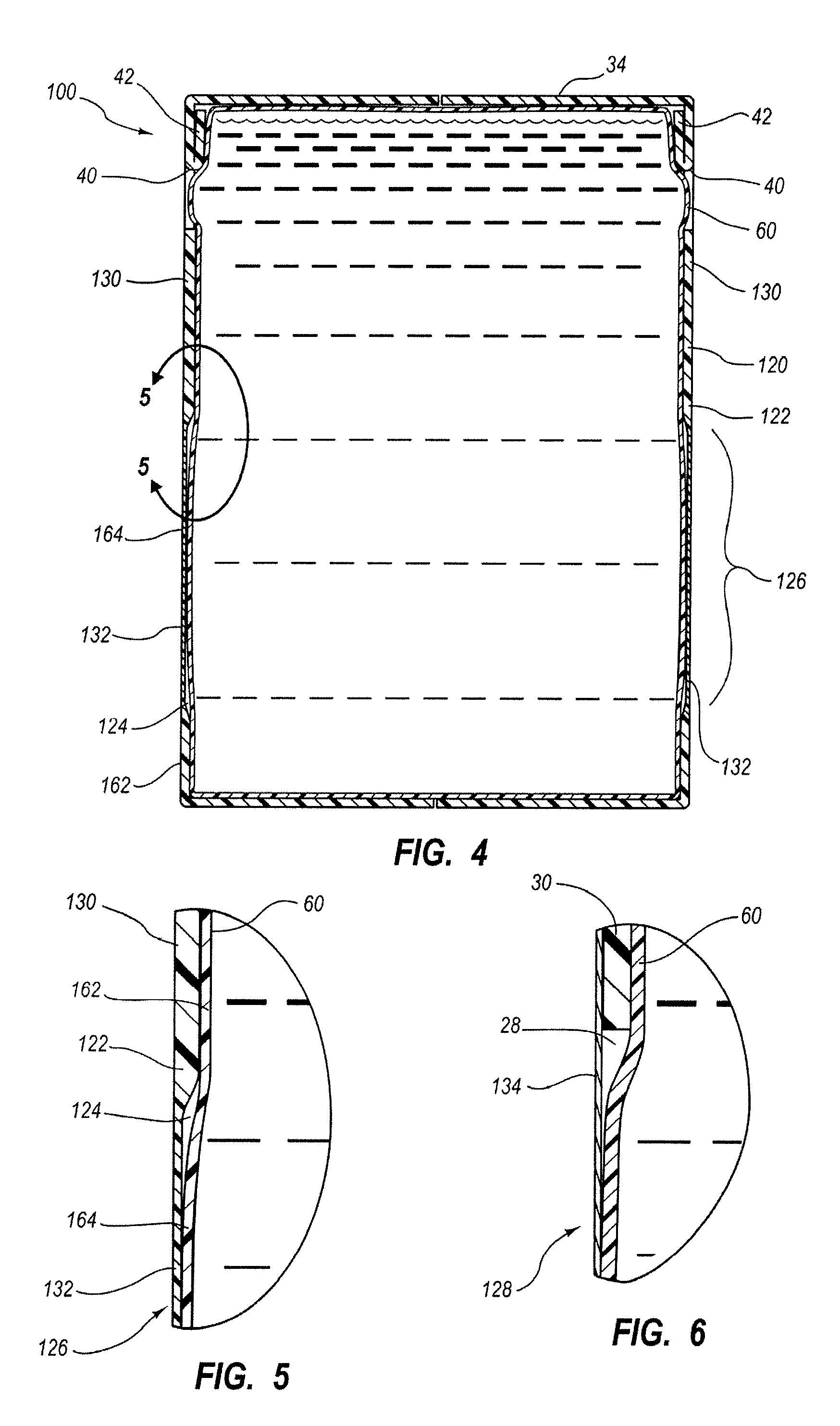
[0066]Reference will now be made to the exemplary embodiments illustrated in the drawings, and specific language will be used herein to describe the same. It will nevertheless be understood that no limitation of the scope of the invention is thereby intended. Alterations and further modifications of the inventive features illustrated herein, and additional applications of the principles of the inventions as illustrated herein, which would occur to one skilled in the relevant art and having possession of this disclosure, are to be considered within the scope of the invention.

[0067]The present invention provides generally a liquid dispenser for use with containers of liquid. The liquid dispenser includes a stand supporting a receptacle sized and shaped to receive a particular sized and shaped liquid storage container therein. The receptacle includes at least one thermal conduction pad positioned in the receptacle so as to be in thermal conductive relationship with the liquid storage c...


PUM


Abstract

A dispenser for relative rapid cooling or heating of the contents of a liquid storage container provides a receptacle for receiving the liquid storage container therein and positioning a thermal transfer portion of the liquid storage container in thermal conductive relationship with a thermal conduction pad associated with the receptacle. Thermal energy is effectively and efficiently transferred from the thermal conduction pad to the liquid in the liquid storage container. The thermal conduction pad is controlled to provide and maintain the desired temperature to the liquid. The liquid is dispensed directly from the container. Various types of containers can be used in the dispenser, with a special bag-in-box container having a inner container and outer box with thermal conduction windows in the box to provide good heat transfer between the thermal conduction pads and the inner container constituting an aspect of the invention. A special rigid container can also be used.

Description

RELATED APPLICATIONS[0001]This is a continuation-in-part of application Ser. No. 11 / 801,824, filed May 10, 2007, now U.S. Pat. No. 7,975,879, incorporated herein by reference.BACKGROUND OF THE INVENTION[0002]1. Field[0003]The present invention relates generally to liquid dispensers, such as water dispensers, which control the temperature of a liquid to be dispensed from the dispenser, and also relates to liquid containers to be used in such liquid dispensers. The present invention also relates to liquid containers.[0004]2. State of the Art[0005]There are numerous types of liquid containers such as bottles, cans, and plastic containers. Where it is desired to maintain liquid in such liquid containers at a particular temperature, the containers are usually placed in a temperature controlled space where the temperature of the container and the liquid contents of the container are allowed to equilibrate with the temperature in the temperature controlled space. For example, to keep the l...

Claims


Application Information

Patent Timeline
Patent Type & Authority Patents(United States)
IPC IPC(8): B65D88/74
CPCB65D5/4204B65D5/4608B65D77/067B67D3/0009B67D3/0067
Inventor GROESBECK, R. CLAY
Owner GROESBECK R CLAY
Learn More