
Wireless Sensor Device And Method For Wirelessly Communicating A Sensed Physical Parameter

a sensor and physical parameter technology, applied in the field of sensors, can solve the problems of increasing the processing power of the sensor, affecting the accuracy of the measurement, and requiring additional memory storage, so as to achieve the effect of long battery life and low power consumption

Active Publication Date: 2012-12-20
ABB (SCHWEIZ) AG
View PDF25 Cites 40 Cited by
  • Summary
  • Abstract
  • Description
  • Claims
  • Application Information

AI Technical Summary

Benefits of technology

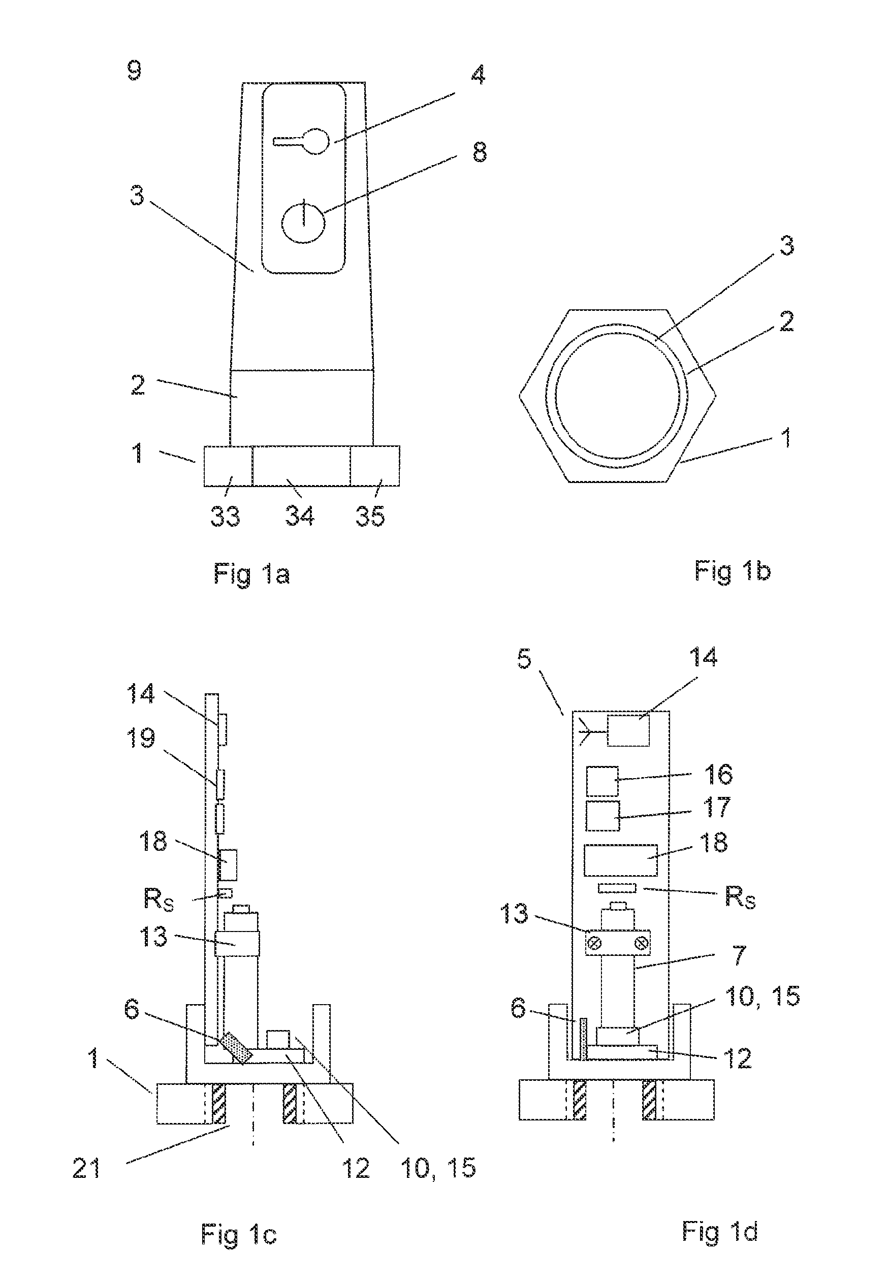
[0013]According to another embodiment of the invention a wireless sensor is disclosed for connection to a wireless network for communication of a sensed physical parameter, said wireless sensor comprising at least one vibration sensor, a processor, a wireless radio transmitter, an independent and self-contained power source and a base part for mounting said wireless sensor on an equipment or structure, wherein the base part is made of metal and is further arranged with fastening means for fixing the wireless sensor to a machine or other structure. This metal base provides a firm attachment and a high thermal capacity or a heat sink in case of component overheating due to a failure. In another embodiment, the base part made of metal is further arranged with a plurality of load bearing surfaces for applying a torque to the base part and fastening said wireless sensor to a machine or other structure with a predetermined torque load. This assures good conduction of vibration to the sensor.
[0018]The low power consumption results in long battery life. The low power and restricted voltage provides an autonomous wireless vibration sensor that complies with requirements such as ATEX and is suitable for use in environments where a potentially explosive gas or vapour can occur.

Problems solved by technology

Vibration is, however, a more demanding phenomenon to monitor with wireless communication because of the large amount of data (e.g. 4 or 8 kB of data) that is needed for the vibration analysis.
However, a disadvantage of this approach is that analysing measurements in the processor of the sensor before wirelessly transmitting such processed data requires additional memory storage, some delays, more processing power and uses more electrical power from the battery.
For example, if a battery should fail with an internal short circuit, that failure should not be allowed to lead to an ignition source.
Thus there is a technically challenging simultaneous requirement for stand alone wireless sensors with an energy source with sufficient energy density to power a sensor for a long period of time versus the requirement to avoid that any component can become hot or overheated during use or failure.

Method used


Image

  • Wireless Sensor Device And Method For Wirelessly Communicating A Sensed Physical Parameter
  • Wireless Sensor Device And Method For Wirelessly Communicating A Sensed Physical Parameter
  • Wireless Sensor Device And Method For Wirelessly Communicating A Sensed Physical Parameter

Examples


Embodiment Construction

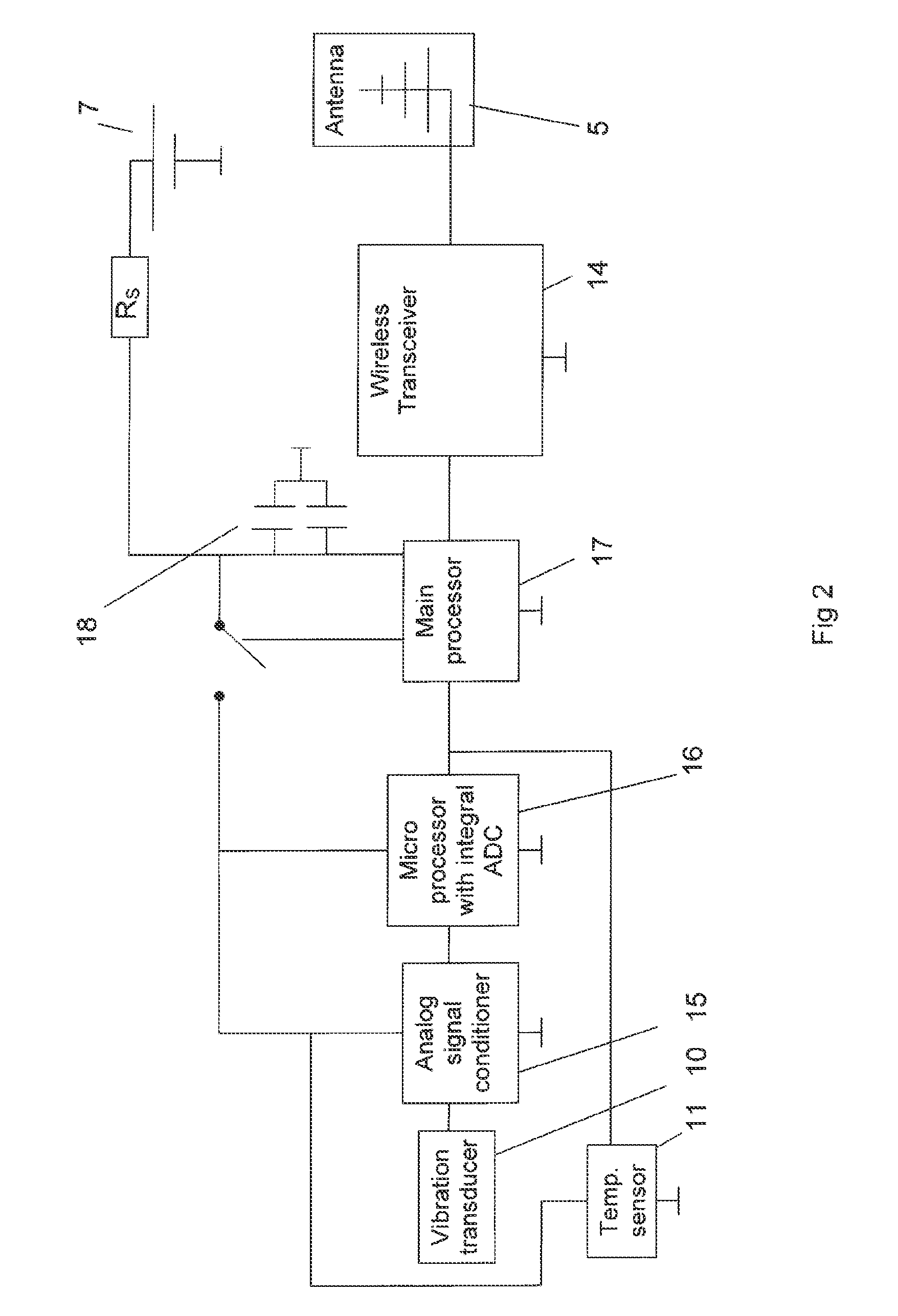
[0026]FIG. 2 shows a schematic block diagram of the wireless vibration sensor. The figure shows a vibration transducer or sensor 10, and analogue signal conditioner 15, and two other processors arranged as a microprocessor with integral A-D conversion 16, a main processor 17. The figure also shows a wireless transceiver 14, and antennae 5 and a battery 7 or other independent power source. A resistor RS is arranged in series between the battery 7 and the other components on pcb 19. The resistor is preferably of the thin film resistor type which is preferred for safety reasons because that type of resistor does not have short circuit as a failure mode. This safety resistor (or resistors) RS limits the maximum voltage that can be drawn from the battery by the components on the pcb to comply with the ATEX requirements.

[0027]The vibration sensor 10 is preferably an accelerometer. A suitable vibration sensor / transducer or accelerometer is of the MEMS-based piezo-resistive bridge transduce...


PUM


Abstract

A wireless vibration sensor suitable for connection to a distributed industrial control system arranged with a wireless network for communication of process data or control information. The wireless vibration sensor includes at least one sensor, a wireless radio transmitter, and a base part for mounting it firmly on equipment or a structure. The wireless sensor is arranged with a battery and a power storage device. A method for powering up the wireless sensor during active cycles is also described.

Description

CROSS-REFERENCE TO RELATED APPLICATIONS[0001]The present application is a continuation of pending International Patent Application PCT / EP2009 / 067786 filed Dec. 22, 2009, which designates the United States and the content of which is incorporated herein by reference.FIELD OF THE INVENTION[0002]The present invention is concerned with a sensor arranged with a wireless transceiver. In particular it is concerned with a wireless sensor for monitoring vibration of a machine. The invention may advantageously be used for condition monitoring of machines in an environment in which combustible or explosive gases can occur.BACKGROUND OF THE INVENTION[0003]In an industrial installation a distributed control system (DCS) or an industrial control system may be equipped with a large number of field devices, including sensors and instruments. Usually such an industrial installation has one or more control rooms and a computer system which are connected by one or more data networks, such as buses or ...

Claims


Application Information

Patent Timeline
IPC IPC(8): G08C19/04G01H17/00
CPCH04Q9/00H04Q2209/43H04Q2209/25H04Q2209/883G01H1/00
Inventor SVOEN, GEIRBANG-STEINSVIK, TOR OLEJUUL, KENNETHFROYSTEIN, SVERRELAG, ORJAN
Owner ABB (SCHWEIZ) AG
Learn More