Partially patterned lead frames and methods of making and using the same in semiconductor packaging

a technology of lead frame and patterned portion, which is applied in the field of semiconductor packaging, can solve the problems of damage and distortion, affecting the production efficiency of semiconductor/solid-state devices, and the finger-like portions of lead frames are quite flimsy and difficult to hold in position, so as to prevent any separation, prevent the propagation of saw force, and eliminate the effect of saw for

Inactive Publication Date: 2005-12-01
UNISEM M BERHAD
View PDF49 Cites 96 Cited by
  • Summary
  • Abstract
  • Description
  • Claims
  • Application Information

AI Technical Summary

Benefits of technology

[0006] The present invention provides a partially patterned lead frame for use in semiconductor packaging. The lead frame is composed of a film having a top surface and a bottom surface. A first region of the film is partially patterned from the top surface but not entirely through the film to the bottom surface. A second region of the film, not patterned from the top surface, forms a chip receiving area for supporting an integrated circuit (IC) chip and a plurality of lead contacts for providing electrical connections to the IC chip. The first region forms trenches in the film and creates a webbed structure that interconnects the second region that is not partially patterned from the top surface. The present invention is also directed to a method of manufacturing partially patterned lead frames and to electronic packages made utilizing the lead frames. The lead frame of the invention has improved structural rigidity because of its web-like, or webbed structure.
[0012] Several advantages arise from the partially patterned lead frame of the present invention. The flat and solid un-etched bottom surface of the lead frame serves as an excellent heat sink during the wire bonding process. This provides even heat transfer for better and more consistent bond quality. Additionally, the solid structure provides a continuous surface for a universal vacuum chuck to hold the lead frame down, thereby making the chip-attachment process more stable and the leads more secure during the subsequent process steps. Awkward clamping of outer edges of the lead frame is eliminated to allow an array-matrix lead frame design and processing without conversion needs. Because the bottom side of the partially patterned lead frame is a flat continuous surface, a universal vacuum chuck may be used to hold down many different sizes of frames. This removes the complication of having to refit the vacuum chuck each time a lead frame of different dimensions is being employed in the packaging process. Also, there is no further need for clamping. The use of a universal vacuum chuck and elimination of clamping enables construction of dual or triple rows of staggered leads on the second region for higher lead counts.
[0017] It is common practice to form the conventional stencil-like lead frames by patterning a photoresist on a strip of metal, or metal film, and etching through the pattern to form the finger-like leads extending outwardly from the chip receiving area. It is also customary to use “tie-bars” between the fingers so that the fingers are kept apart during the various process steps, as was shown in FIGS. 3a and 3b. The present invention alleviates the problem of the lack of structural rigidity of the lead frame by forming a web-like, partially patterned lead frame instead of a stencil-like lead frame.
[0019] The removal of embedded metal through the saw thickness, or streets, in the webbed portions has several advantages, including the elimination of the saw forces propagating throughout the lead frame structure, and hence, the prevention of the delamination at the metal-plastic interfaces. Also, the electrical isolation through back-etching enables strip testing prior to any sawing or singulation, or for that matter, prior to any further processing steps. After the back patterning, the remaining and exposed metal portions on the bottom surface can then be flash finished with any number of solderable materials through immersion-tin dipping or electroless-nickel plating. The ELGA package uses the FC of the ELPF package, however, with LGA pads for connection to the next level of packaging.
[0020] In order to prevent any separation between the molding material and other components of the package during manufacturing, the present invention also teaches how to form locking features on the exposed vertical walls of the recessed webbed portions of the partially etched lead frame, such as on the side walls of the leads, that will come in contact with the molding material, such as a resin. As an alternative, it is also taught to form “lips” on the edges of the chip-pad and lead contacts so as to capture the molding material under each lip, thereby making it difficult for the molding material to separate from the mating surfaces.

Problems solved by technology

Conventional lead frames generally lack structural rigidity.
The finger-like portions of lead frames can be quite flimsy and difficult to hold in position.
This lends to handling flaws, damage and distortion in assembly processes and complicated wire bonding situations.
A failure to optimize the bonding parameters to compensate for the mechanical instability of the lead frame can result in poor bond adhesion, and hence poor quality and poor reliability of the bond.
The prior art has not shown any lead frames that can withstand the stresses encountered in current semiconductor packaging processes and that can be manufactured in a cost effective manner.

Method used


Image

  • Partially patterned lead frames and methods of making and using the same in semiconductor packaging
  • Partially patterned lead frames and methods of making and using the same in semiconductor packaging
  • Partially patterned lead frames and methods of making and using the same in semiconductor packaging

Examples


Embodiment Construction

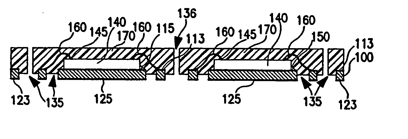
[0056]FIGS. 4-15b and FIGS. 16-24b show different embodiments of forming a partially patterned lead frame package with lead counts comparable to that of near-chip scale packages (CSPs). The method of the invention improves the automation of the manufacturing line and the quality and reliability of the packages made therefrom. This is accomplished by performing a major portion of the manufacturing process steps with a partially patterned metal film formed into a web-like lead frame on one side. In contrast with conventionally punched through stencil-like lead frames, the lead frame used in the invention is partially patterned on one side and is solid and flat on the other side. This construction is improved both mechanically and thermally, and performs without distortion or deformation during the chip-attach, wire bond, and encapsulation processes. After the chip attach and wire bonding process steps are completed and the chip and wire bonds are affixed and hermetically encapsulated ...


PUM

PropertyMeasurementUnit
thicknessaaaaaaaaaa
thicknessaaaaaaaaaa
thicknessaaaaaaaaaa

Abstract

A method of making a lead frame and a partially patterned lead frame package with near-chip scale packaging (CSP) lead-counts is disclosed, wherein the method lends itself to better automation of the manufacturing line as well as to improving the quality and reliability of the packages produced therefrom. This is accomplished by performing a major portion of the manufacturing process steps with a partially patterned strip of metal formed into a web-like lead frame on one side, in contrast with the conventional fully etched stencil-like lead frames, so that the web-like lead frame, which is solid and flat on the other side is also rigid mechanically and robust thermally to perform without distortion or deformation during the chip-attach and wire bond processes. The bottom side of the metal lead frame is patterned to isolate the chip-pad and the wire bond contacts only after the front side, including the chip and wires, is hermetically sealed with an encapsulant. The resultant package being electrically isolated enables strip testing and reliable singulation without having to cut into any additional metal. The use of the instant partially patterned lead frame in making ELP, ELPF and ELGA-type CSPs is also disclosed.

Description

FIELD OF THE INVENTION [0001] The invention relates to electronic packaging in general, and more particularly, to a partially patterned lead frame and a method for making and using the same. The partially patterned lead frame is stronger and more stable than conventional lead frames. The sturdiness of the partially patterned lead frame improves the process of manufacturing lead frame packages and enhances the overall reliability of the end product. BACKGROUND OF THE INVENTION [0002] In making electronic packages that use lead frames, there are several process steps that subject the lead frames to mechanical and thermal stresses. The finer geometries of current lead frames and the ever-increasing integration of circuits on semiconductor chips have resulted in processing that places even greater stress on the lead frames. Finely configured lead frames often resemble very delicate embroidery, or stencil-like metal structures that tend to bend, break, disfigure and deform easily. (See F...

Claims


Application Information

Patent Timeline
Patent Type & Authority Applications(United States)
IPC IPC(8): H01L21/44H01L21/48H01L21/56H01L23/31H01L23/495
CPCH01L21/4832H01L24/49H01L2924/014H01L24/48Y10T29/49121H01L2224/49171H01L2224/48465H01L2224/32245H01L2224/92247H01L24/97H01L2924/01047H01L2924/01078H01L2224/92H01L2924/01005H01L2224/48091H01L2924/01075H01L2224/48247H01L2924/01006H01L2924/14H01L23/49582H01L2924/01082H01L2924/01033H01L21/4842H01L2924/01028H01L2924/01013H01L21/561H01L21/56H01L2224/45147H01L2924/0105H01L2924/30105H01L24/45H01L2924/01046H01L2924/01029H01L2924/01079H01L2224/16245H01L23/3107H01L2224/97H01L23/3114H01L2224/73265H01L2224/85201H01L2924/18301H01L2924/00014H01L2224/85H01L2224/81H01L2224/83H01L2924/00H01L2224/05554H01L2224/45015H01L2224/45124H01L2924/10161H01L2924/10162H01L2924/12042H01L2924/181H01L2924/351H01L2924/00012
Inventor ISLAM, SHAFIDULANTONIO, ROMARICO SANTOS SAN
Owner UNISEM M BERHAD
Why Eureka
Try Eureka