Airbag with low-volume structure

a low-volume, airbag technology, applied in the direction of pedestrian/occupant safety arrangement, vehicular safety arrangment, vehicle components, etc., can solve the problems of high head acceleration, head injuries, packaging challenges, etc., and achieve the effect of increasing the structural stiffness of the airbag

Active Publication Date: 2014-01-07
AUTOLIV ASP INC
View PDF10 Cites 33 Cited by
  • Summary
  • Abstract
  • Description
  • Claims
  • Application Information

AI Technical Summary

Benefits of technology

[0009]According to one embodiment, at least two side tethers may be provided of which each is arranged on either lateral side of the airbag. Each side tether may be attached to the first section and one of the second and third sections or to a transitional bend between the second and third section, thereby limiting an enveloping volume of the airbag.
[0012]Uninflated islands in the airbag may create increased structural stiffness of the airbag because a relative movement between opposing surfaces is restricted. They can also create folding lines for the airbag during deployment.

Problems solved by technology

This constitutes a potentially dangerous situation, where a forward excursion may result in high head accelerations and possibly head injuries from a seat back of a seat located in front of the seat occupant.
Airbags of current designs pose packaging challenges, based in part on the assumption that a large inflated volume is needed in order to provide the airbag with the sufficient energy absorption during a crash due to the force of the occupant impact.
However, problems have been noted to occur with airbags of current design in that they can often be difficult to install in vehicles such as small or compact models where space in the passenger compartment is at a premium.
Moreover, such large and bulky airbags often require complex gas generator units in order to guarantee that the airbag will promptly and properly inflate during a crash.
These large and bulky gas generators create additional problems because not only do they further increase the size and complexity of the airbag system, but are often also very expensive.
More importantly, multiple and complex gas generators can be very difficult to assemble, install, or repair.
In an airplane with possibly hundreds of seats, large gas generators provided for every seat significantly increase the cost and weight of a passive safety system.

Method used


Image

  • Airbag with low-volume structure
  • Airbag with low-volume structure
  • Airbag with low-volume structure

Examples


second embodiment

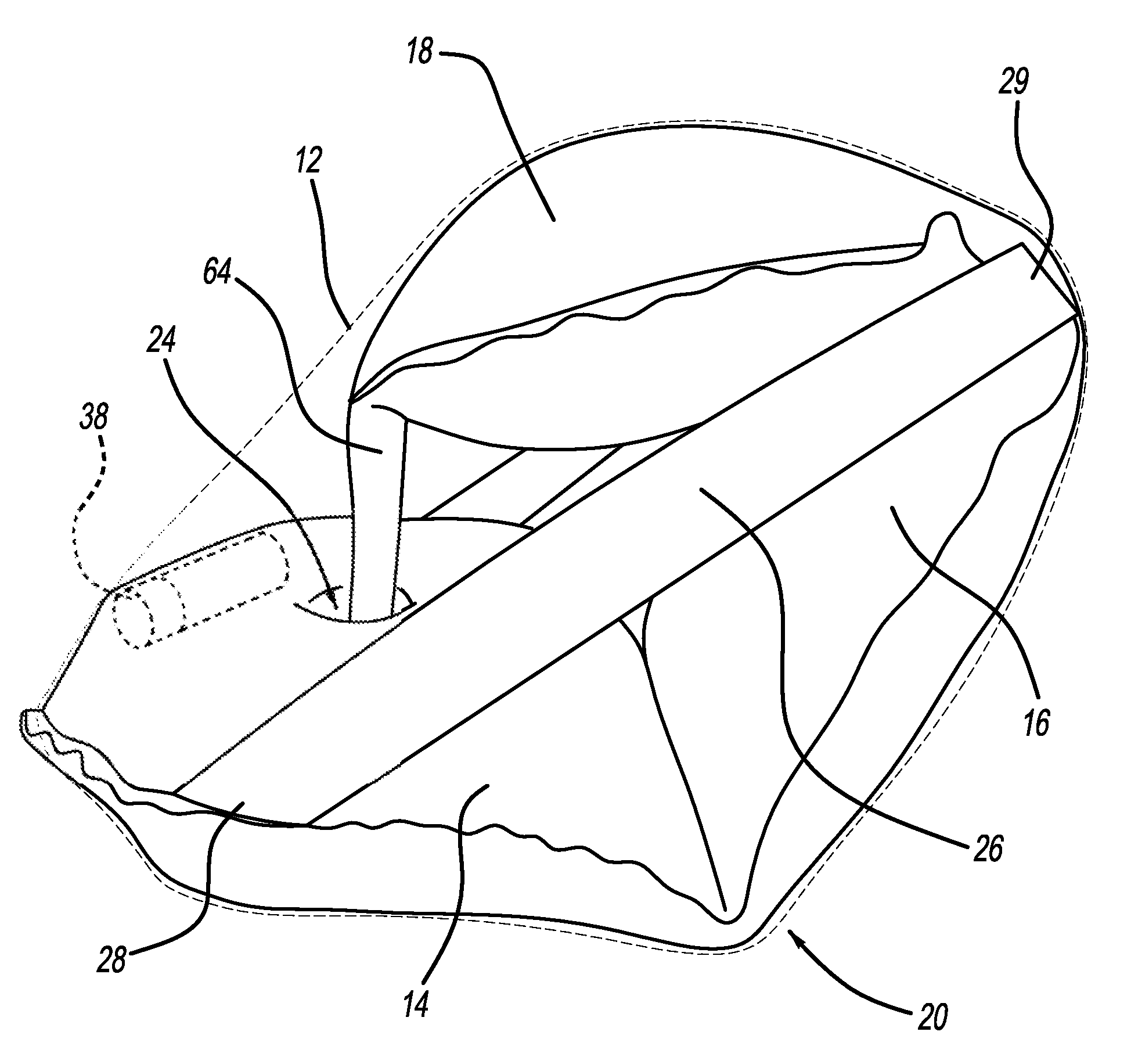
[0040]FIGS. 4 and 5 show an airbag 20 according to a FIG. 4 shows the airbag in the inflated state, while FIG. 5 provides a plan view onto the inner fabric layer 34. Airbag 20 is also based on the concept that the enveloping volume 12 is greater than the volume of the airbag itself, where the enveloping volume 12 defines a volume that a conventional airbag would need to fill for providing outer surfaces that correspond to those of the shown embodiment.

[0041]The outer contour of the enveloping volume 12 of airbag 20, however, resembles a quadrilateral shape rather than a triangle. This is due to the end portion 24 being connected to the third section 18 via an intermediate uninflated portion 64. This uninflated portion 64 acts like a tether that allows the third portion 18 to form a smaller angle relative to the first portion 14 and to extend nearly parallel to the first portion 14.

[0042]The side tethers 26 are attached to the attachment points 28 on the first section 14 as describe...

third embodiment

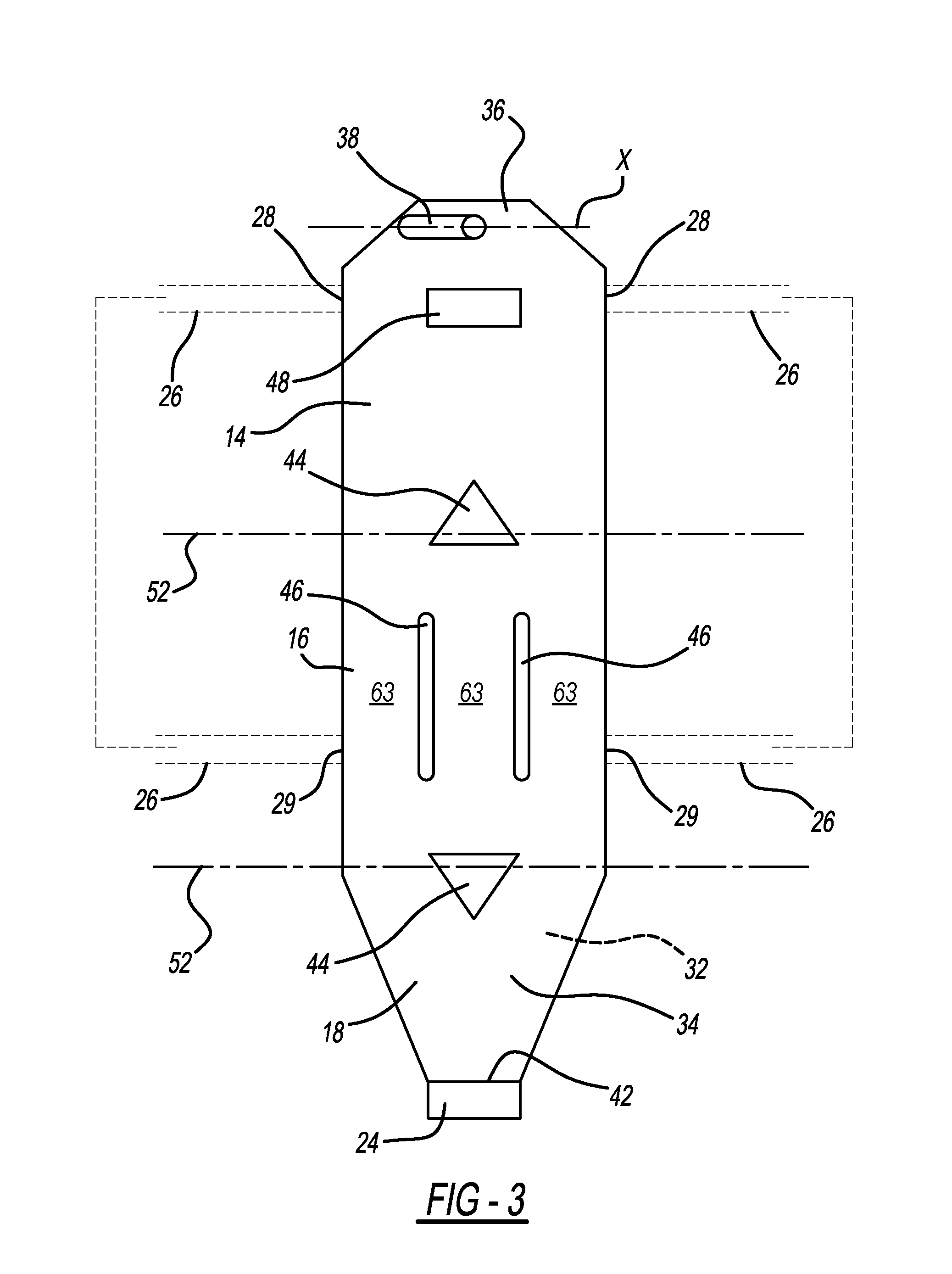
[0043]Now referring to FIG. 6 an airbag 30 is shown in a plan view onto the inner fabric layer 34. The airbag 30 has one of the uninflated islands 44 defining the bend axis 52 between the second section 16 and the third section 18. The other bend axis 52 between the first section 14 and the second section 16 is defined by an uninflated island 66 that generally extends from a port area 68 to the bend axis 52 between the first section 14 and the second section 16.

[0044]The port area 68 is shown as bounded by a broken line that indicates a seam 76 that does not extend through both the outer fabric layer 32 and the inner fabric layer 34. Instead, the port 70 is in fluid communication with the first section 14.

[0045]In a similar manner, an end portion 74 on the third section 18 has a port 72 in fluid communication with the third portion 18. Thus, the end portion 74 is not an uninflated area and is surrounded by seam 76 indicated by a broken line that does not extend through the outer fab...


PUM


Abstract

A frontal airbag has a first section, a second section, and a third section, the second section being in fluid communication with both the first and the third section. The first, second and third sections form a triangular structure upon inflation of the airbag. A gas generator is attached to the first section and in fluid communication with the first section. An end portion on the third section remote from the second sections attached to the first section in an area between the gas generator and the second section. Two side tethers attached to the first section and to one of the second and third sections or near transitional bend between the second and third section provide resistance against flattening of the airbag after inflation. The first section and the third section are directly attached to each other by a seam, by an adhesive, or by lamination.

Description

FIELD OF THE INVENTION[0001]The invention relates to a frontal airbag arrangement for the protection of seat occupants in a motor vehicle.BACKGROUND OF THE INVENTION[0002]Airbags have been credited for saving lives by damping impact of a motor vehicle crash on a vehicle occupant. Not only frontal impact airbags are in use, but also side impact airbags, such as side curtain airbags expanding from the roof line of a vehicle or airbags arranged in a center console or armrest between two car seats. After the gas generator is triggered, the airbag unfolds and provides energy absorption for the seat occupant. An airbag arranged in an armrest pushes itself between the seats and between seat occupants sitting next to each other. Another known airbag design provides an airbag in the vicinity of the center tunnel of the vehicle that inflates above the heads of the vehicle occupants to protect the occupants in the event of a vehicle rollover or of an “off-side” impact.[0003]Airbags are designe...

Claims


Application Information

Patent Timeline
Patent Type & Authority Patents(United States)
IPC IPC(8): B60R21/2338B60R21/233
CPCB60R21/2338B60R21/233B60R2021/0093B60R2021/23386B60R21/231
Inventor SCHNEIDER, DAVID W.MACOCHA, CHANDLER
Owner AUTOLIV ASP INC
Why Eureka
Try Eureka