Moving table MRI with frequency-encoding in the z-direction

a technology of frequency encoding and moving table, applied in the field of moving table, can solve the problems of not being able to collect data, not being able to use all known systems, and not being able to achieve ideal images

Inactive Publication Date: 2005-05-10
GENERAL ELECTRIC CO
View PDF19 Cites 43 Cited by
  • Summary
  • Abstract
  • Description
  • Claims
  • Application Information

AI Technical Summary

Benefits of technology

[0008]It would therefore be desirable to have a new method and apparatus that allows ...

Problems solved by technology

These slab-boundary artifacts result in non-ideal images.
These methods however, move the slab-selective excitation while keeping the table stationary rather than moving the table and keeping the slab position stationary.
As a result, these methods are limited by the inherent optimal imaging volume of the MR scanner.
These methods employ phase encoding in the z-di...

Method used


Image

  • Moving table MRI with frequency-encoding in the z-direction
  • Moving table MRI with frequency-encoding in the z-direction
  • Moving table MRI with frequency-encoding in the z-direction

Examples


Embodiment Construction

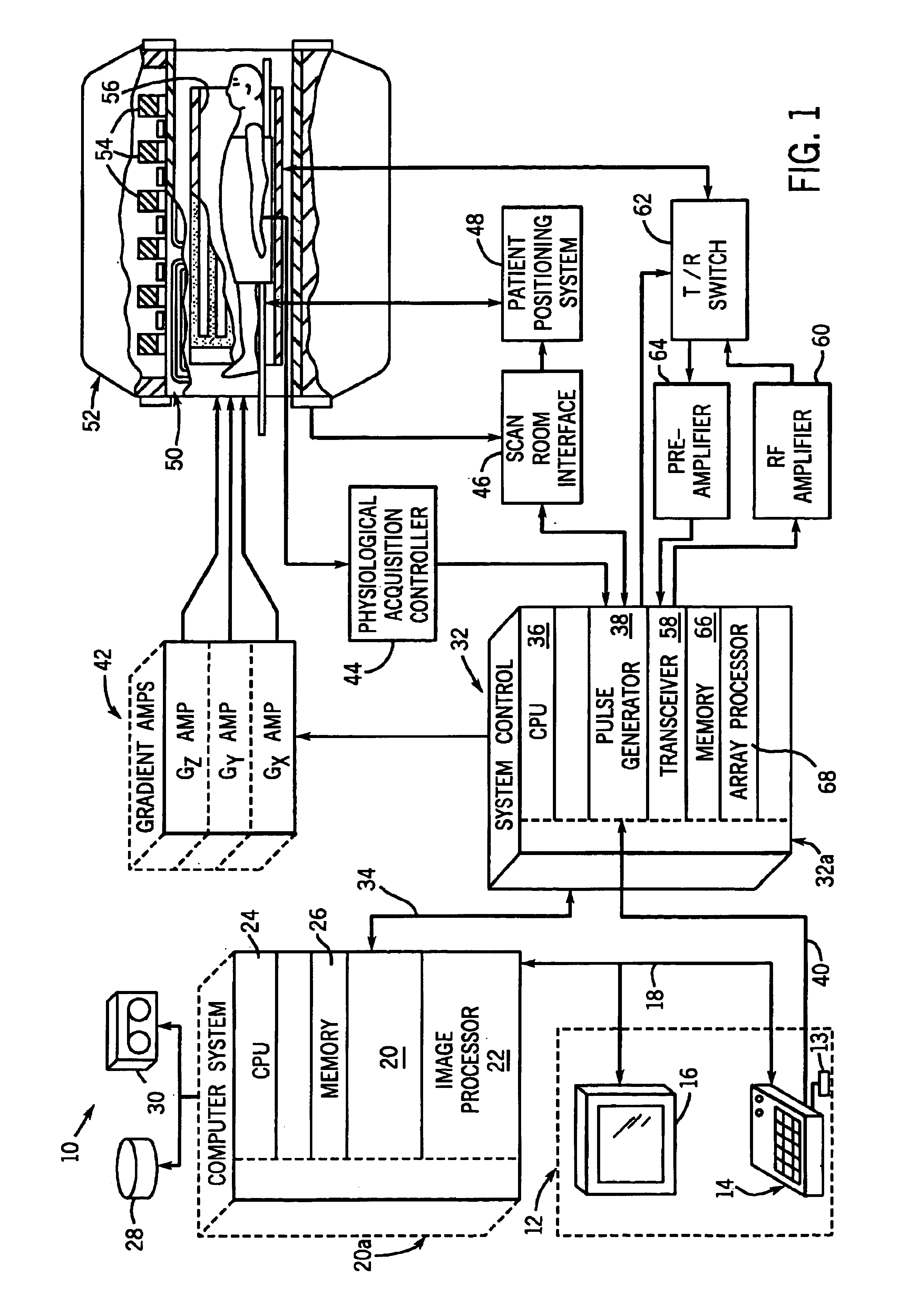
[0028]Referring to FIG. 1, the major components of a preferred magnetic resonance imaging (MRI) system 10 incorporating the present invention are shown. The operation of the system is controlled from an operator console 12 which includes a keyboard or other input device 13, a control panel 14, and a display 16. The console 12 communicates through a link 18 with a separate computer system 20 that enables an operator to control the production and display of images on the screen 16. The computer system 20 includes a number of modules which communicate with each other through a backplane 20a. These include an image processor module 22, a CPU module 24 and a memory module 26, known in the art as a frame buffer for storing image data arrays. The computer system 20 is linked to disk storage 28 and tape drive 30 for storage of image data and programs, and communicates with a separate system control 32 through a high speed serial link 34. The input device 13 can include a mouse, joystick, ke...


PUM


Abstract

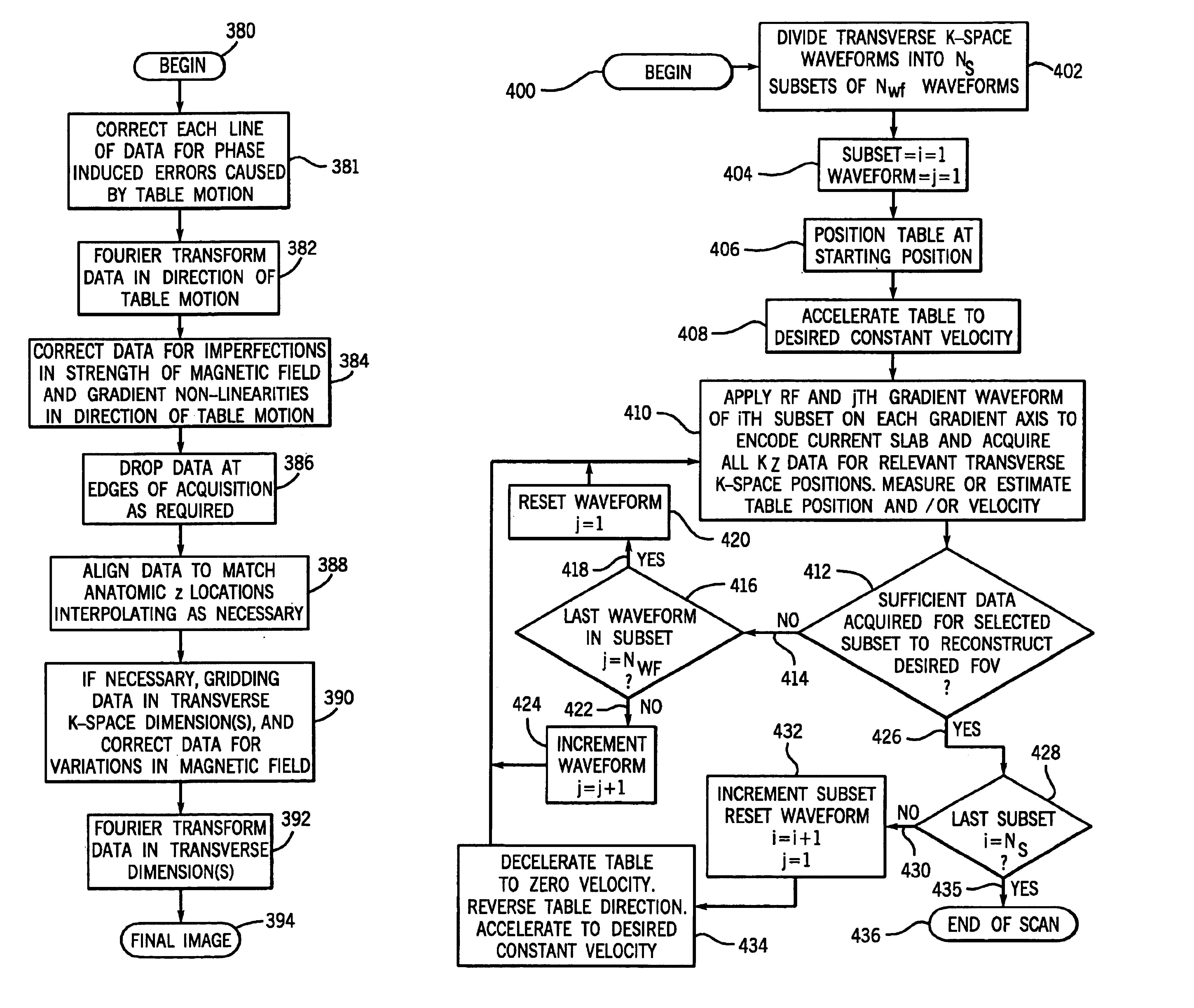
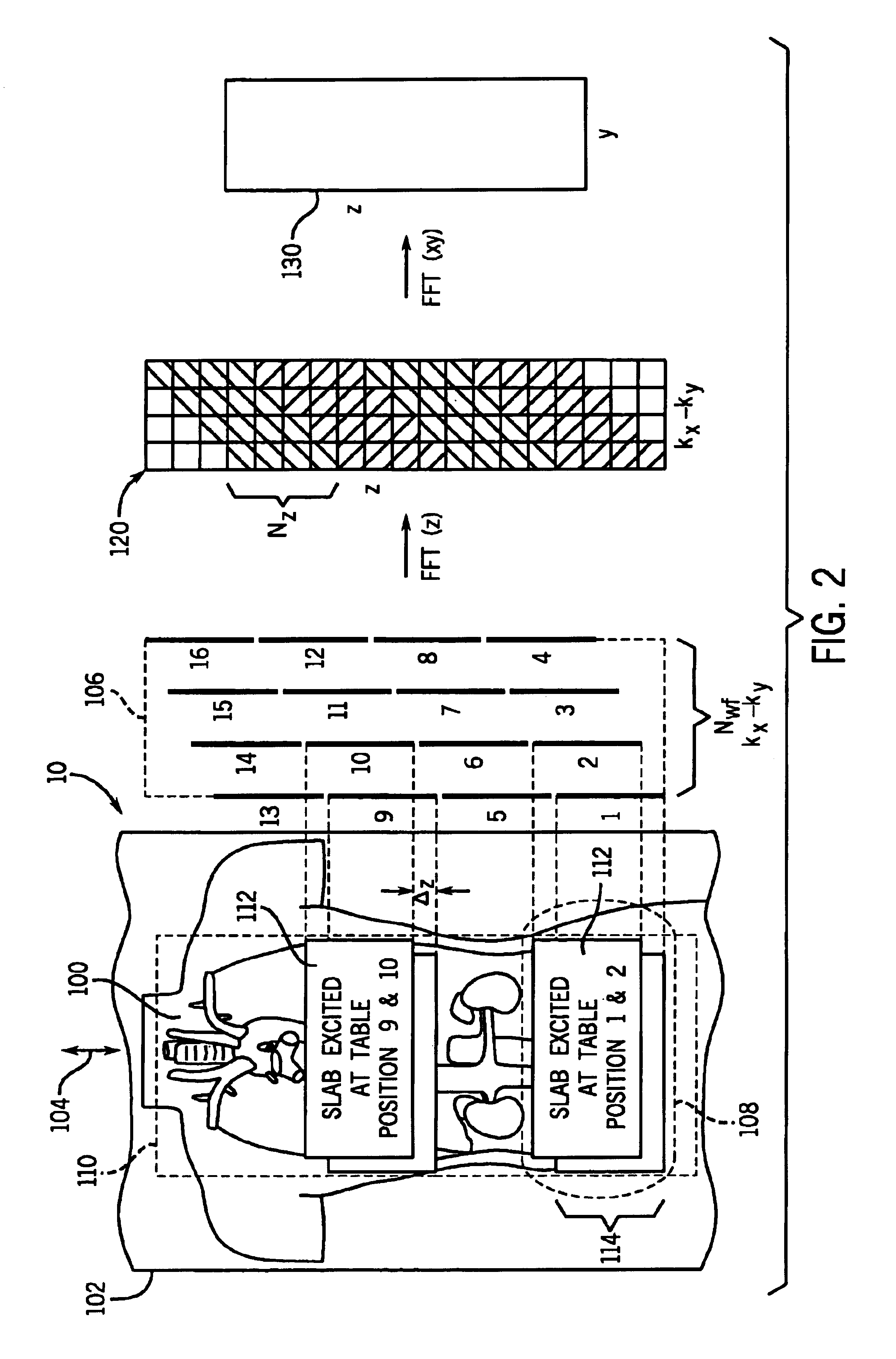
A system and method are disclosed using continuous table motion while acquiring data to reconstruct MR images across a large FOV without significant slab-boundary artifacts that reduces acquisition time. At each table position, full z-encoding data are acquired for a subset of the transverse k-space data. The table is moved through a number of positions over the desired FOV and MR data are acquired over the plurality of table positions. Since full z-data are acquired for each slab, the data can be Fourier transformed in z, interpolated, sorted, and aligned to match anatomic z locations. The fully sampled and aligned data is then Fourier transformed in remaining dimension(s) to reconstruct the final image that is free of slab-boundary artifacts.

Description

CROSS-REFERENCE TO RELATED APPLICATIONS[0001]The present application is a continuation of U.S. patent application Ser. No. 09 / 682,699 filed Oct. 5, 2001, now U.S. Pat. No. 6,794,869 which is a continuation-in-part of U.S. patent application Ser. No. 09 / 681,420 filed Mar. 30, 2001 now U.S. Pat. No. 6,801,034.BACKGROUND OF THE INVENTION[0002]The present invention relates generally to an improved method of medical imaging over large areas, and more particularly, to a method and apparatus of acquiring magnetic resonance (MR) images over an area that is greater than the optimal imaging area of an MR scanner using continuous table movement through the MR scanner without incurring slab-boundary artifacts.[0003]When a substance such as human tissue is subjected to a uniform magnetic field (polarizing field B0), the individual magnetic moments of the spins in the tissue attempt to align with this polarizing field, but process about it in random order at their characteristic Larmor frequency....

Claims


Application Information

Patent Timeline
IPC IPC(8): G01R33/563G01R33/54G01R33/28G01R33/30A61B5/055
CPCG01R33/28G01R33/56383G01R33/56375G01R33/54
Inventor BRITTAIN, JEAN HELEN
Owner GENERAL ELECTRIC CO
Why Eureka
Try Eureka