Self-organizing sensor node network

a sensor node and network technology, applied in the field of self-organizing systems, can solve the problems of inefficiency and wasted energy, and it is not possible to deploy each node, so as to reduce power consumption, improve coverage, and reduce the minimum acceptable degree of coverage

Inactive Publication Date: 2006-11-09
DUKE UNIV +2
View PDF11 Cites 138 Cited by
  • Summary
  • Abstract
  • Description
  • Claims
  • Application Information

AI Technical Summary

Benefits of technology

[0005] Methods and apparatus are described by which a number of sensor nodes (“nodes”) can self-organize so as to reduce energy consumption or improve coverage of a surveillance field, establishing communication between the nodes, estimating a location for each node within the network, determining a coverage of each node, deactivating any redundant nodes (i.e. those that only provide coverage also provided by other nodes) and repositioning nodes if necessary. The deactivation of nodes reduces energy consumption of the network, for example by reducing the number of inter-node communications.
[0007] A reduced number of nodes needed to provide the same coverage and connectivity of the surveillance area as the original deployment can be selected by switching off the redundant nodes with full overlapping coverage. Nodes may also be deactivated to reduce power consumption while retaining a minimum acceptable degree of coverage. Mobile nodes may further be provided which reposition themselves to improve coverage and / or reduce energy requirements of inter-node communications, as a tradeoff between communication and surveillance tasks. One or more mobile nodes may reposition themselves so as to reduce communications energy requirements.
[0008] An improved monitoring system comprises a plurality of nodes, nodes having a sensing capability, communication with other nodes, computation ability, and (optionally) mobility. The plurality of nodes forms a communications network, the mobile nodes moveable within the surveillance field so as to reduce communication energy requirements of the monitoring system, or to improve coverage. The self-configuration of the system can take into account known or estimated paths of objects to be tracked through the surveillance field.
[0009] An example improved system includes a protocol for self-organizing a node network for tracking, a location estimation strategy that works even where not all nodes have GPS capabilities, state management of nodes in a dense node network, and a mobility strategy that compromises between a surveillance task and the goal of minimizing communication energy.

Problems solved by technology

However, it may not be possible to deploy each node into an optimal location within the surveillance field.
A large number of nodes can be deployed to ensure coverage, but this leads to inefficiency and wasted energy, due to overlapping coverage.

Method used


Image

  • Self-organizing sensor node network
  • Self-organizing sensor node network
  • Self-organizing sensor node network

Examples


example scenario

Protocol Operation in Example Scenario

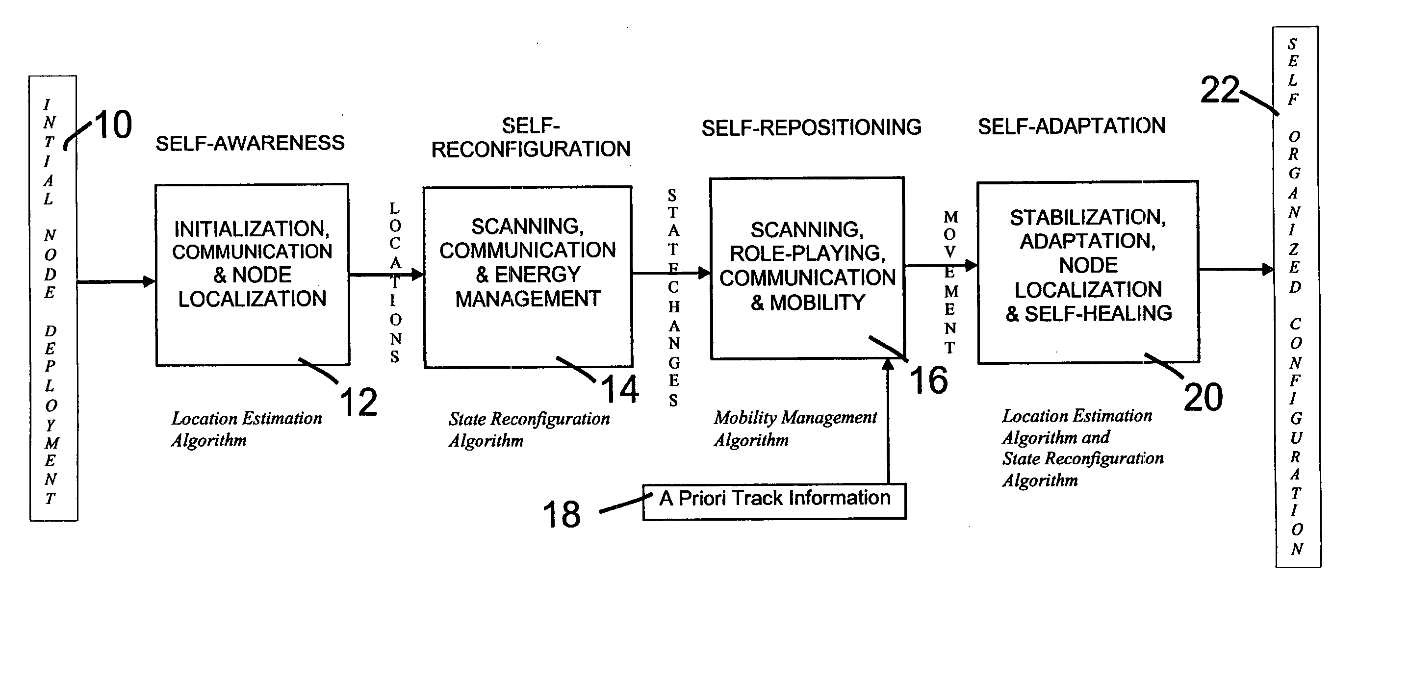
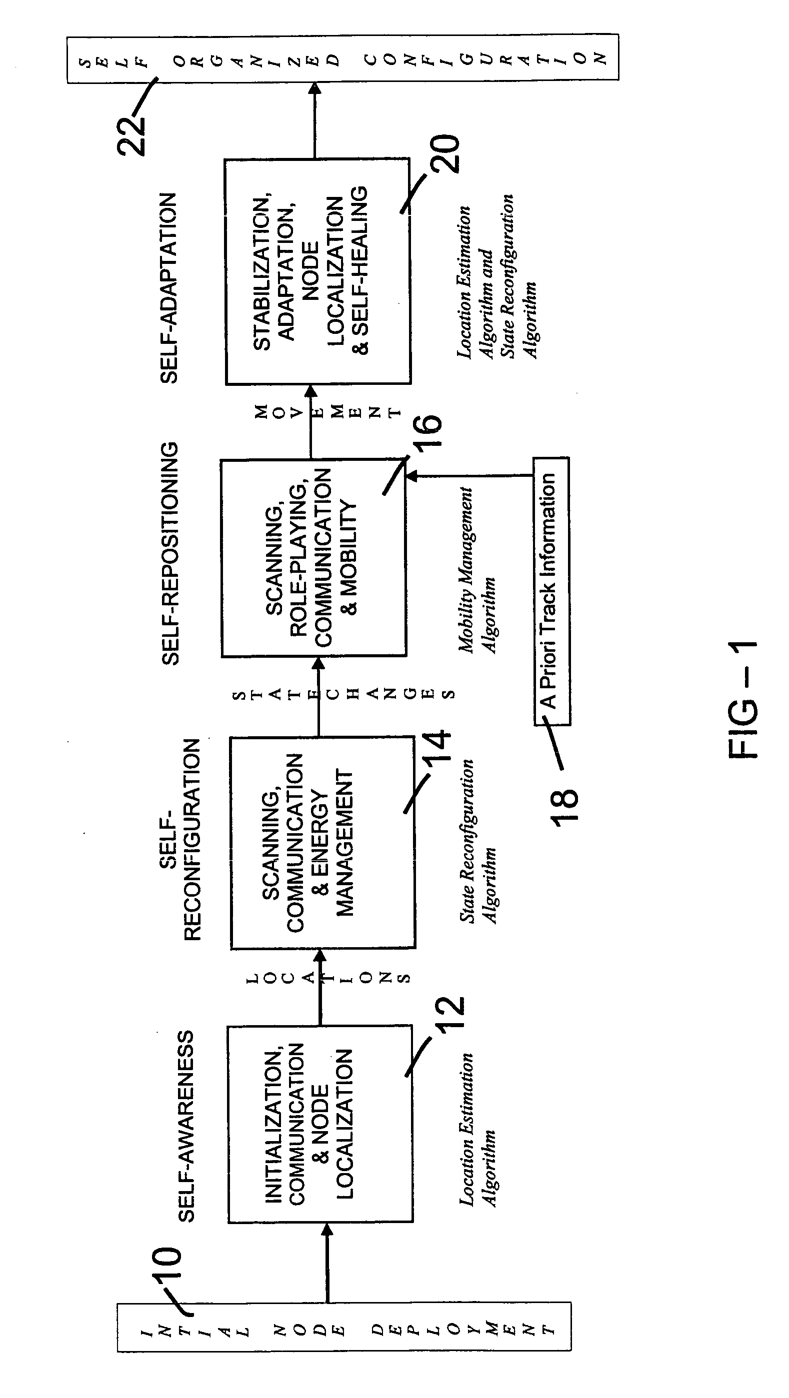
[0114] Operation of an improved protocol according to the present invention in an example scenario may use the following stages:

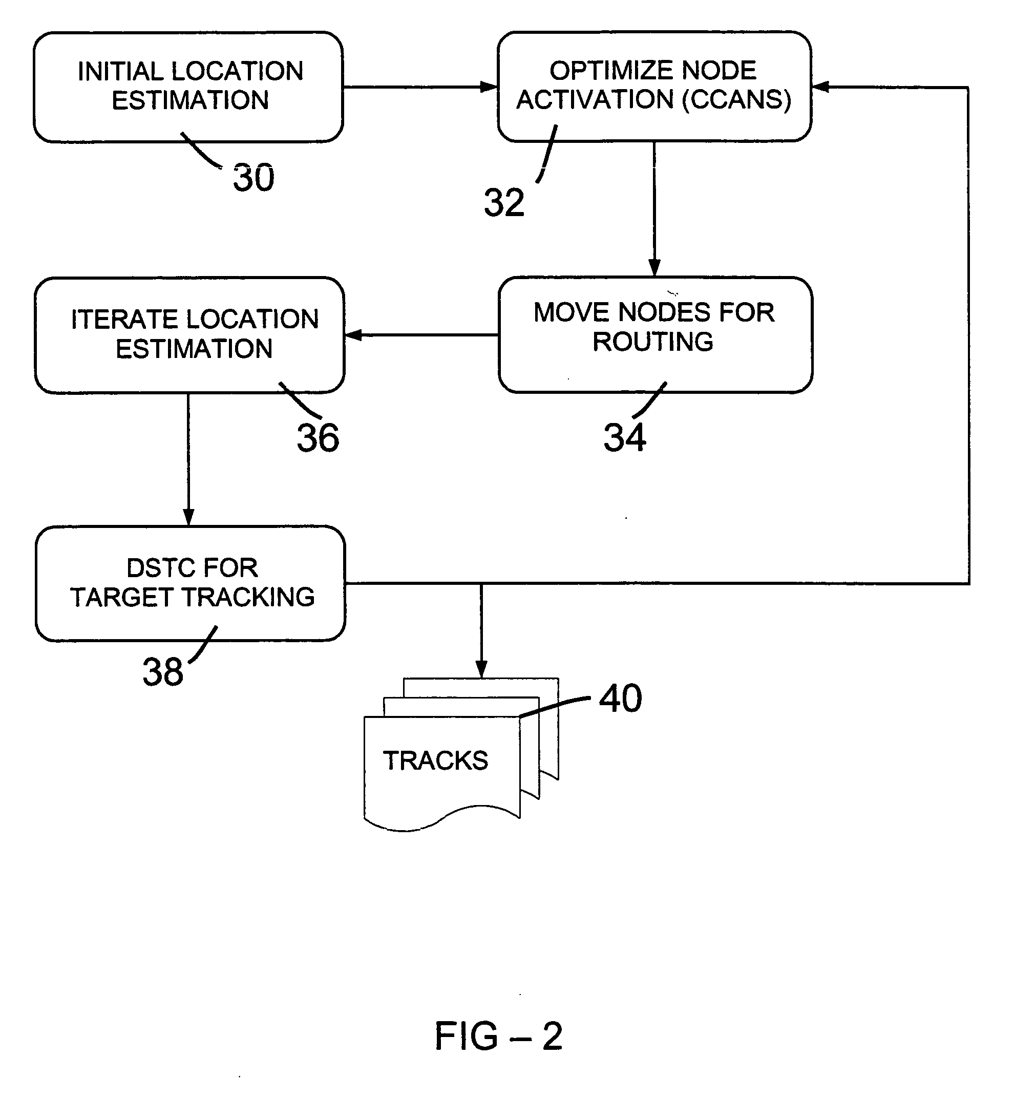
[0115] Stage 1: (Real-time DSTC Tracking)

[0116] 1) A target (mobile robot) enters combat zone

[0117] 2) Virtual & real (static & mobile) nodes running the DSTC algorithm track the path of the target.

[0118] 3) The track is displayed on a screen.

[0119] Stage 2: (Self-organization Simulation)

[0120] 4) A Network Simulator (NS) reads the initial network configuration, creates and positions simulated nodes as per the initial deployment. Nodes are all active at the onset

[0121] 5) Location Estimation algorithm determines locations of all simulated nodes (self-awareness)

[0122] 6) Nodes can either remain active or become inactive (switching off node services) to minimize energy consumption and maximize node coverage yet ensuring connectivity, based on a token passing mechanism. The density of active nodes may become consid...


PUM


Abstract

An improved network of sensor nodes can self-organize so as to reduce energy consumption and / or improve coverage of a surveillance field. Nodes within the network may be dynamically activated or deactivated so as to lengthen network lifetime and / or enhance sensor coverage of the surveillance field.

Description

REFERENCE TO RELATED APPLICATION [0001] This application claims priority of U.S. Provisional Patent Application Ser. No. 60 / 646,735, filed Jan. 25, 2005, the entire content of which is incorporated herein by reference.STATEMENT OF GOVERNMENT SPONSORSHIP [0002] The research carried out in connection with this invention was supported by the Defense Advanced Research Projects Agency (DARPA) and managed by the Army Research Office under Emergent Surveillance Plexus MURI Award No. DAAD19-01-1-0504; ONR Grant No. N66001-0-1-8946; and U.S. Army Grant No. DACA72-00-C-0021. The U.S. Government may have rights in this invention.FIELD OF THE INVENTION [0003] The present invention relates to self-organizing systems, such as a sensor node network. BACKGROUND OF THE INVENTION [0004] Sensor node networks can be used to monitor a surveillance field, for example by tracking objects such as vehicles within the surveillance field. However, it may not be possible to deploy each node into an optimal loc...

Claims


Application Information

Patent Timeline
Patent Type & Authority Applications(United States)
IPC IPC(8): G06F15/173
CPCH04L41/0816H04L41/0833H04L41/0853H04L41/12H04W4/006H04W84/18H04L67/12Y02B60/50H04W4/001H04W16/18H04W4/50H04W4/38Y02D30/70
Inventor BISWAS, PRATIKZOU, YIPHOHA, SHASHICHAKRABARTY, KRISHNENDURAMANATHAN, PARAMESWARANKESIDIS, GEORGESUNDARAM, NIVEDITHATONG, LUN
Owner DUKE UNIV
Why Eureka
Try Eureka