Damp-proof power distribution cabinet for rainy areas

A technology for power distribution cabinets and regions, applied in the field of moisture-proof power distribution cabinets, can solve problems such as affecting ventilation, increasing heat generation, and increasing power consumption, achieving good results and high gas temperature.

Active Publication Date: 2021-09-07
江苏电博仕能源装备有限公司
View PDF3 Cites 3 Cited by
  • Summary
  • Abstract
  • Description
  • Claims
  • Application Information

AI Technical Summary

Problems solved by technology

[0002] There are a large number of electrical components installed inside the power distribution cabinet, so it is required to keep the interior relatively dry when using it. When the humidity in the power distribution cabinet is too high, it will not only accelerate the aging and damage speed of the electrical components, but also may cause safety accidents;
[0003] Existing power distribution cabinets generally use vents equipped with filters for passive heat dissipation, but for some rainy areas, when it rains, the air humidity is very high, and it is easy for humid air to enter the power distribution cabinet through the vents during passive heat dissipation. However, if some drying layers are directly placed at the vents, it will affect the ventilation of passive heat dissipation, resulting in poor passive heat dissipation under normal conditions, and in rainy days, due to the increase in indoor activity, so Generally, the power consumption will increase relatively, so the load of the power distribution cabinet will increase, and the heat will increase. It is obviously difficult for passive heat dissipation to meet the high load heat dissipation of the power distribution cabinet. Therefore, how to reasonably solve the above problems is what we need to consider

Method used


Image

  • Damp-proof power distribution cabinet for rainy areas
  • Damp-proof power distribution cabinet for rainy areas
  • Damp-proof power distribution cabinet for rainy areas

Examples


Embodiment 1

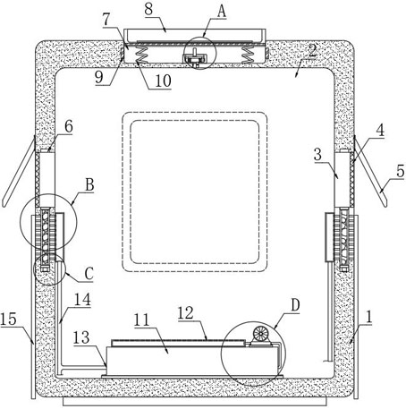
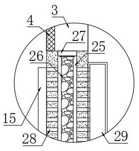
[0028] refer to Figure 1-5 , a moisture-proof power distribution cabinet for rainy areas, including a housing 1, an installation chamber 2 is provided inside the housing 1, vents 3 are provided on the inner walls of both sides of the installation chamber 2, and both sides of the housing 1 are installed with useful For the inclined baffles 5 for rain protection, each inclined baffle 5 is located at the corresponding vent 3, and a filter 4 is installed in each vent 3, and the filter 4 is used to filter dust when passively dissipating heat. The inner bottom of each vent 3 is provided with a sliding groove 25, and the inner top of each vent 3 is provided with a limiting groove 6. When the activated carbon plate 26 is raised, the sliding bar 27 above will snap into the corresponding In the limiting groove 6, an active carbon plate 26 is arranged in each slide groove 25. The active carbon plate 26 is a plate made of active carbon and a screen frame, which can dry the air. The upper...

Embodiment approach

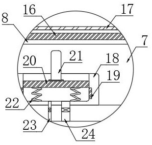
[0030] As an embodiment of the present invention, as an embodiment of the present invention, in order to allow the activated carbon plate 26 to rise, a conductive box 18 is installed on the inner bottom of the trigger groove 7, and a conductive box 18 for sliding up and down is provided in the conductive box 18. plate 20, the lower end of the conductive plate 20 is elastically connected to the inner bottom of the corresponding conductive box 18 through a plurality of connection springs 22, and the inner walls of both sides of the conductive box 18 are provided with a second conductive sheet 19 that cooperates with the conductive plate 20, and the conductive plate The upper end of 20 is fixedly connected with the rod 21 matched with the lower end of the water collection box 8, the bottom space of the conductive box 18 communicates with the interior space of the installation chamber 2 through the one-way air intake pipe 23 and the one-way exhaust pipe 24, and the one-way air intak...

Embodiment 2

[0039] refer to Figure 6-7 , The difference between this embodiment and Embodiment 1 is that a rectangular cavity 32 is provided in the installation box 11, the main pipe 13 runs through the rectangular cavity 32, the part of the main pipe 13 located in the rectangular cavity 32 is in a zigzag shape, and the main pipe 13 is located in the rectangular cavity 32. The inner part of the cavity 32 is made of heat-conducting material, and the rectangular cavity 32 is filled with a phase-change material, which can collect heat, and the installation box 11 is made of a heat-insulating material. Both the pipe 14 and the two second hollow plates 29 are made of heat-insulating materials, so as to prevent heat from re-entering the installation chamber 2 during the transfer process.

[0040] In this embodiment, after the fan 31 is started in rainy days, when the power usage increases in rainy days, the load of the power distribution cabinet is large, and the internal heat dissipation of t...


PUM


Abstract

The present invention discloses a damp-proof power distribution cabinet for rainy areas. The cabinet comprises a shell, an installation chamber is arranged in the shell, ventilation openings are formed in the inner walls of the two sides of the installation chamber respectively, a filter screen is installed in each ventilation opening, a sliding groove is formed in the inner bottom of each ventilation opening, a limiting groove is formed in the inner top of each ventilation opening, an activated carbon plate is arranged in each sliding groove, the upper end and the lower end of each activated carbon plate are fixedly connected with sliding strips, and each sliding strip is slidably connected with the inner wall of the corresponding sliding groove. According to the power distribution cabinet, the activated carbon plate can be lifted in rainy days, active heat dissipation is carried out while wet air is dried, the heat dissipation effect is good, a heat collection structure is further arranged, collected heat can be used for evaporation of water on the drying layer after raining, and the drying effect of the drying layer is guaranteed.

Description

technical field [0001] The invention relates to the field of electric equipment, in particular to a moisture-proof power distribution cabinet for rainy areas. Background technique [0002] There are a large number of electrical components installed inside the power distribution cabinet, so it is required to keep the interior relatively dry when using it. When the humidity in the power distribution cabinet is too high, it will not only accelerate the aging and damage speed of the electrical components, but also may cause safety accidents; [0003] Existing power distribution cabinets generally use vents equipped with filters for passive heat dissipation, but for some rainy areas, when it rains, the air humidity is very high, and it is easy for humid air to enter the power distribution cabinet through the vents during passive heat dissipation. However, if some drying layers are directly placed at the vents, it will affect the ventilation of passive heat dissipation, resulting ...

Claims


Application Information

Patent Timeline
Patent Type & Authority Applications(China)
IPC IPC(8): H02B1/30H02B1/56H02B1/28B01D46/10B01D53/26
CPCH02B1/30H02B1/565H02B1/28B01D46/10B01D53/261B01D2253/102B01D2259/40086B01D2259/4009
Inventor 杜学伟
Owner 江苏电博仕能源装备有限公司
Why Eureka
Try Eureka