a multi-speed gearbox
A technology of gearbox and clutch, applied in the direction of vehicle gearbox, multi-gear ratio transmission device, transmission device, etc., can solve the problem of unable to meet the requirements of gear and speed ratio, and achieve the effect of short transmission path and high transmission accuracy
- Summary
- Abstract
- Description
- Claims
- Application Information
AI Technical Summary
Problems solved by technology
Method used
Image
Examples
Embodiment 1
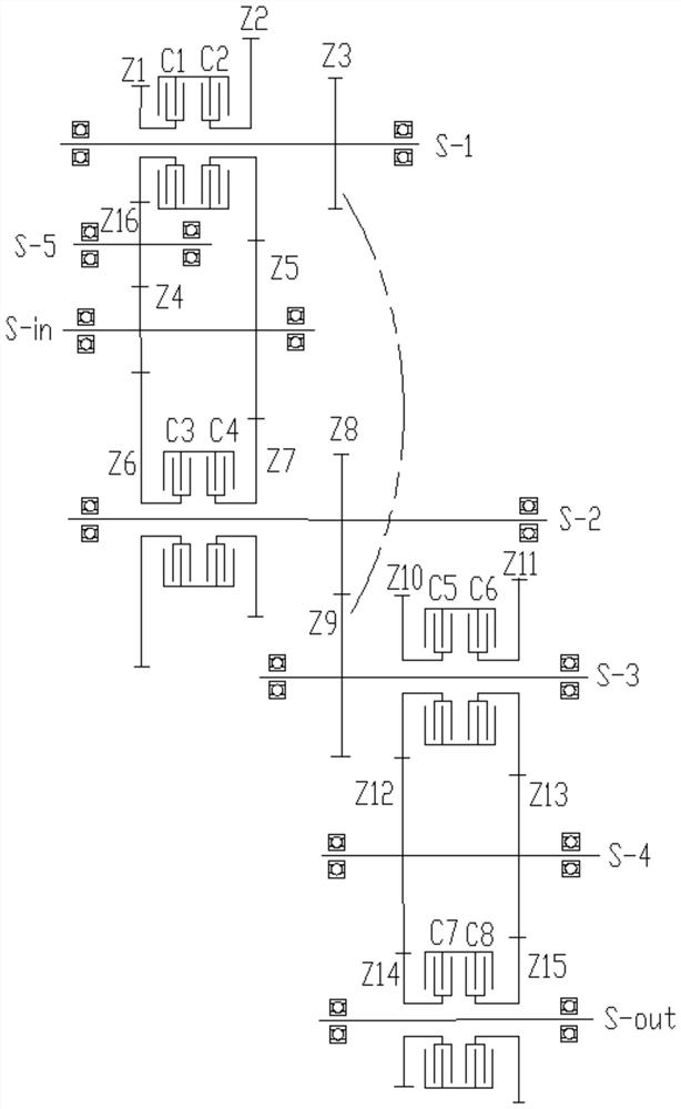
[0071] Such as figure 1 As shown, the multi-speed gearbox of this embodiment includes an input shaft S-in, an intermediate shaft S-1 to an intermediate shaft S-5, and an output shaft S-out, wherein:
[0072] The input shaft S-in is provided with a fixed gear Z4 and a fixed gear Z5,
[0073] The intermediate shaft S-1 is provided with a fixed gear Z3, a floating gear Z1 installed through a clutch C1, and a floating gear Z2 installed through a clutch C2,
[0074] The intermediate shaft S-2 is provided with a fixed gear Z8, a floating gear Z6 installed through a clutch C3, and a floating gear Z7 installed through a clutch C4,
[0075] The intermediate shaft S-3 is provided with a fixed gear Z9, a floating gear Z10 installed through a clutch C5, and a floating gear Z11 installed through a clutch C6,
[0076] The intermediate shaft S-4 is provided with a fixed gear Z12 and a fixed gear Z13,
[0077] The intermediate shaft S-5 is provided with a fixed gear Z16,
[0078] The outp...
Embodiment 2
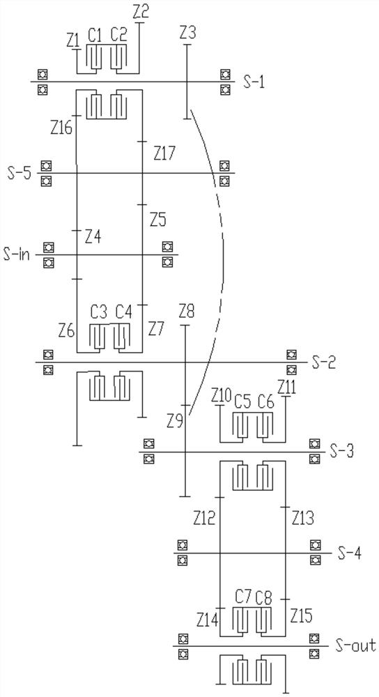
[0099] Such as figure 2 As shown, on the basis of the structure of the first embodiment above, the multi-speed gearbox of this embodiment adds a fixed gear Z17 on the intermediate shaft S-5, the fixed gear Z17 meshes with the floating gear Z2, and the fixed gear Z17 meshes with the floating gear Z2. The gear Z17 meshes with the fixed gear Z5, and the floating gear Z2 does not mesh with the fixed gear Z5. The gearbox realizes the mode of 8 forward gears / 8 reverse gears, wherein:
[0100] Forward 1st gear: the clutch C3, the clutch C5 and the clutch C7 are in a combined state, and the specific transmission path is: the power of the input shaft S-in sequentially passes through the fixed gear Z4, the floating gear Z6, the intermediate shaft S-2, the fixed gear Gear Z8, fixed gear Z9, intermediate shaft S-3, floating gear Z10, fixed gear Z12 and floating gear Z14 are transmitted to the output shaft S-out;
[0101] Forward 2nd gear: the clutch C3, the clutch C5 and the clutch C8 a...
Embodiment 3
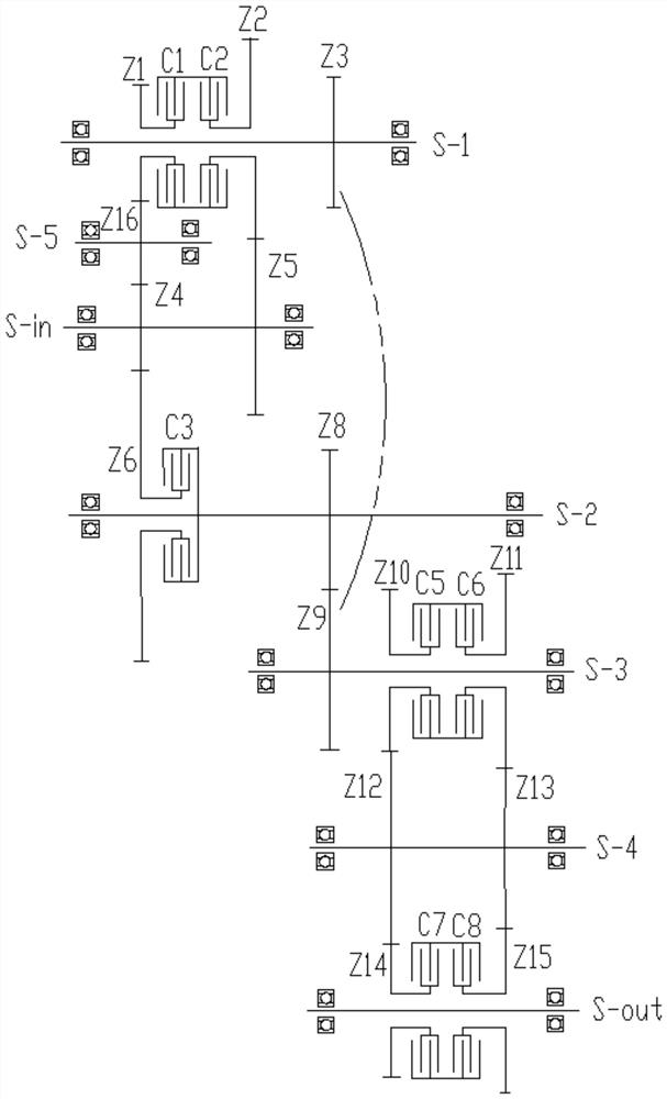
[0118] Such as image 3 As shown, the multi-speed gearbox of this embodiment is based on the structure of the first embodiment above, and the clutch C4 and the corresponding floating gear Z7 on the intermediate shaft S-2 are removed, that is, the clutch C4 and the floating gear Z7 do not participate in the transmission , the gearbox realizes the mode of forward 8 gears / backward 4 gears, wherein:
[0119] Forward 1st gear: the clutch C2, the clutch C5 and the clutch C7 are in a combined state, and the specific transmission path is: the power of the input shaft S-in sequentially passes through the fixed gear Z5, the floating gear Z2, the intermediate shaft S-1, the fixed Gear Z3, fixed gear Z9, intermediate shaft S-3, floating gear Z10, fixed gear Z12 and floating gear Z14 are transmitted to the output shaft S-out;
[0120] Forward 2nd gear: the clutch C2, the clutch C5 and the clutch C8 are in a combined state, and the specific transmission path is: the power of the input shaf...
PUM
 Abstract
Description
Claims
Application Information
 - R&D
- Intellectual Property
- Life Sciences
- Materials
- Tech Scout
- Unparalleled Data Quality
- Higher Quality Content
- 60% Fewer Hallucinations
Browse by: Latest US Patents, China's latest patents, Technical Efficacy Thesaurus, Application Domain, Technology Topic, Popular Technical Reports.
© 2025 PatSnap. All rights reserved.Legal|Privacy policy|Modern Slavery Act Transparency Statement|Sitemap|About US| Contact US: help@patsnap.com


