
Evaluation method of a non-contact displacement sensor self-recovery anti-shock device

A displacement sensor, non-contact technology, applied in the field of displacement sensors, can solve the problems of cumbersome use process, unsuitable occasions with harsh working environment, sensor collision damage, etc., to achieve the effect of attenuating impact destructive force

Active Publication Date: 2022-04-22
NAVAL UNIV OF ENG PLA
View PDF5 Cites 0 Cited by
  • Summary
  • Abstract
  • Description
  • Claims
  • Application Information

AI Technical Summary

Problems solved by technology

[0003] The main problem existing in this type of equipment is that, for example, the eddy current displacement sensor (application publication number: CN203489834U) mainly aims at the temperature drift problem of the eddy current sensor, and provides an eddy current displacement sensor that can effectively reduce the temperature drift. It is reflected in the cumbersome use process. It is necessary to set the characteristic slope and other parameters of the sensor to perform displacement measurement. At the same time, the measurement signal is easily disturbed during long-distance transmission and cannot be applied to occasions with harsh working environments.
In view of the above deficiencies, the integrated structure intelligent bus eddy current displacement sensor (application publication number: CN105953715A) provides a highly integrated, high precision, intelligent electric sensor with the ability of online compensation of temperature environment changes and the ability of fault self-diagnosis. The eddy current displacement sensor, however, has weak impact resistance, and it is easy to cause the sensor to be damaged by collision in the event of large impact and vibration, and its adaptability to large displacement under impact conditions is weak

Method used


Image

  • Evaluation method of a non-contact displacement sensor self-recovery anti-shock device
  • Evaluation method of a non-contact displacement sensor self-recovery anti-shock device
  • Evaluation method of a non-contact displacement sensor self-recovery anti-shock device

Examples


Embodiment approach

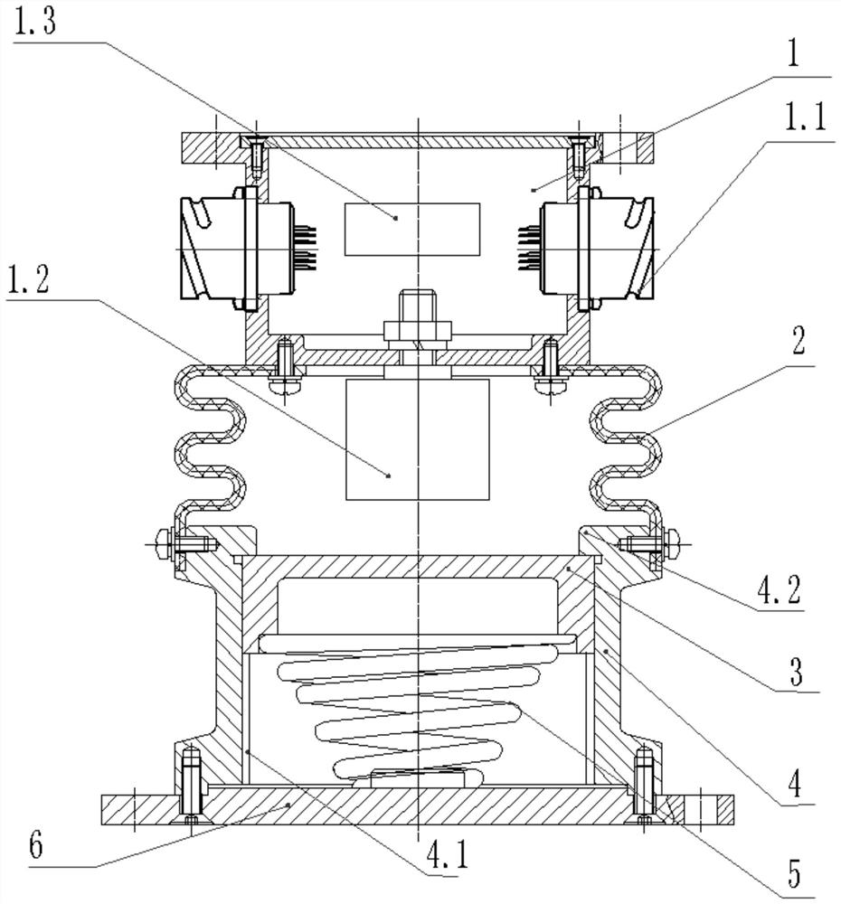
[0031] As an implementation, the displacement sensor body assembly 1 includes a housing, an electrical connector 1.1, a sensor probe 1.2 and a signal processing module 1.3; the electrical connector 1.1 is arranged on both sides of the housing, and the signal processing module 1.3 is arranged on Inside the casing, the sensor probe 1.2 is arranged on the lower surface of the casing. The maximum allowable deformation of the bellows 2 of the capsule body can adapt to the limit displacement change of the sensor probe 1.2 and the detection plate 3 during a large impact;

[0032] As an implementation, linear guide rails 4.1 are vertically provided on the inner walls around the limit housing 4, and the detection board 3 can move up and down along the guide rails 4.1. The upper end surface of the limit housing 4 is in contact with the detection plate through the limit mechanism 4.2. The linear guide rail 4.1 on the inner wall of the limit housing 4 has a motion guiding function, which...


PUM


Abstract

The invention relates to an evaluation method of a non-contact displacement sensor self-recovery anti-shock device. The device specifically includes a displacement sensor body assembly, a capsule bellows, a limit housing and an impact-resistant self-resetting assembly. The bellows of the capsule elastically closes and protects the sensor probe and the detection plate, and its elastic deformation capacity can adapt to the displacement change under the condition of large impact; the linear guide rail and the limit stop structure are designed inside the limit housing, which can constrain the detection plate along the vertical direction It moves and limits the maximum vertical displacement of the detection board; the two ends of the self-restoring coil spring are respectively connected to the detection board and the limit housing base to play the role of impact buffer, and the detection board returns to the initial position after the impact; a kind of resistance Impact structure performance evaluation method, guide the design of impact structure parameters and evaluate the structure reset state after impact. The invention has the advantages of high measurement precision, strong impact resistance, good adaptability, etc., and can realize high-precision displacement monitoring and measurement in a large impact environment.

Description

technical field [0001] The invention relates to the field of displacement sensors, in particular to an evaluation method of an anti-shock self-recovery device of a non-contact displacement sensor. Background technique [0002] In the environment of ships and vehicles, there are external impact disturbances, which will cause a large displacement change at the measurement position of the displacement sensor, causing the sensor probe to collide with the detection plate, causing damage to the sensor. If a displacement sensor with a larger range is selected to set a safe enough gap to avoid impact, there are problems of low measurement accuracy and high cost of the sensor. Therefore, in some occasions with large shock and strong vibration, in order to achieve reliable and high-precision displacement measurement, the displacement sensor must be designed for shock resistance to obtain excellent shock adaptability. [0003] The main problem existing in this type of equipment is tha...

Claims


Application Information

Patent Timeline
Patent Type & Authority Patents(China)
IPC IPC(8): G01B21/00
CPCG01B21/00
Inventor 施亮程光辉刘松邱元燃潘逊
Owner NAVAL UNIV OF ENG PLA
Learn More