Unlock instant, AI-driven research and patent intelligence for your innovation.
Bionic support buffer structure and non-pneumatic tires
What is Al technical title?
Al technical title is built by PatSnap Al team. It summarizes the technical point description of the patent document.
A technology of non-pneumatic tires and buffer structures, applied in non-pneumatic tires, tire measurement, tire parts, etc., can solve the problem that the support buffer structure cannot resist the influence of linear acceleration and angular acceleration.
Active Publication Date: 2022-03-04
JIHUA LAB
View PDF14 Cites 0 Cited by
Summary
Abstract
Description
Claims
Application Information
AI Technical Summary
This helps you quickly interpret patents by identifying the three key elements:
Problems solved by technology
Method used
Benefits of technology
Problems solved by technology
[0004] The main purpose of the present invention is to provide a bionic support and buffer structure, aiming to solve the technical problem that the current support and buffer structure cannot resist the influence of high linear acceleration and angular acceleration during the rotation process
Method used
Image
Click on the blue label to locate the original text in one second.
Reading with bidirectional positioning of images and text.
Examples
Embodiment 1
[0046] In the embodiment of the present invention, such as Figure 1-5 As shown, the bionic support buffer structure includes:
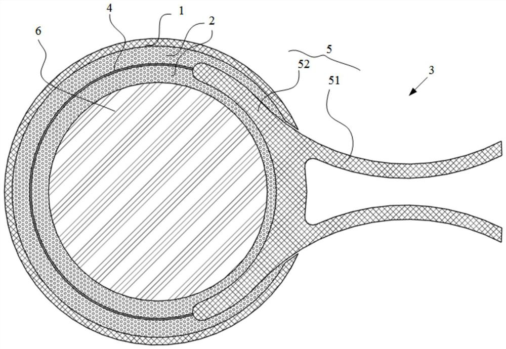
[0047] Housing 1, the housing 1 is formed with a receiving chamber with an opening;
[0048] The support buffer assembly 3, the support buffer assembly 3 includes a receiving part and a supporting part, the receiving part is hollow and located in the receiving cavity, the supporting part extends out of the receiving cavity through the opening of the housing, And used to connect external components;
[0049] a buffer body 6, the buffer body 6 is located in the receiving portion; and
[0050] The cooling buffer 2 is provided between the outer wall of the buffer body 6 and the inner wall of the receiving part, and between the inner wall of the housing 1 and the outer wall of the receiving part.
[0051] In a specific implementation process, the part of the support buffer assembly 3 inside the casing 1 is the receiving part, and the part outside the cas...
Embodiment 2
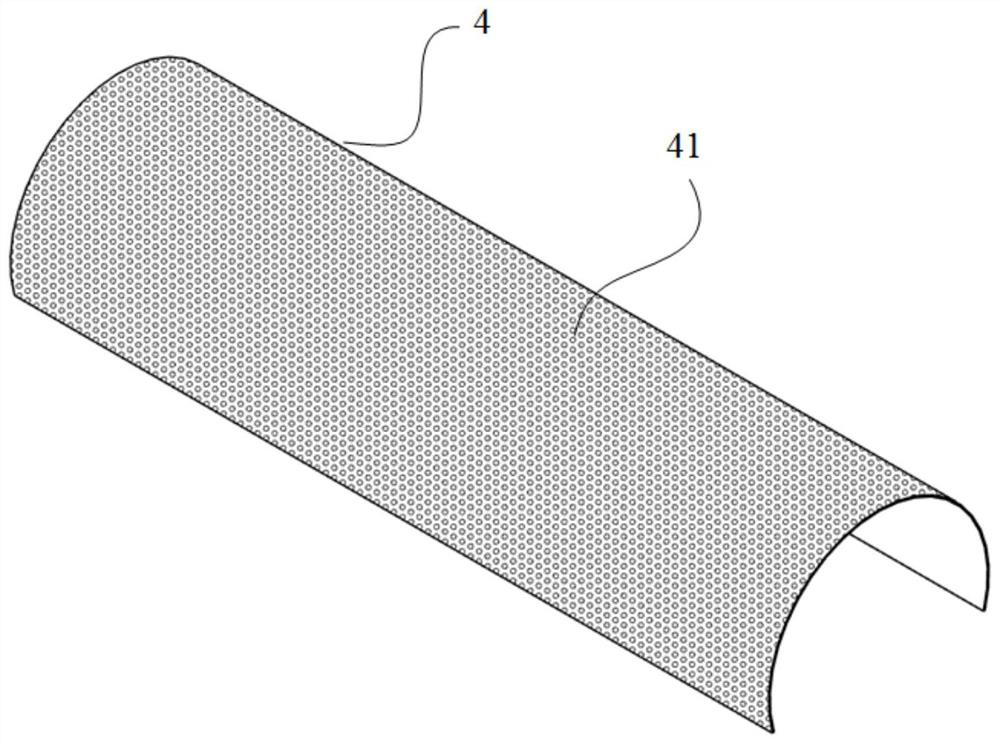
[0066] On the basis of the above embodiments, the housing 1 in this embodiment has a spherical structure, and accordingly, the buffer body 6 is also configured as a spherical structure. The cooling buffer 2 is filled between the buffer body 6 and the housing 1, and the cooling buffer 2 is embedded with a telescopic belt 4, and the telescopic belt 4 wraps half of the outer side of the buffer body 6. Of course, there is also a cooling buffer between the two. piece 2. The other half of the structure of the buffer body 6 is wrapped by one end of the support member 5 , and the cooling buffer member 2 is filled between the two, and the stretchable belt 4 and the support member 5 wrap the entire buffer body 6 . The other end of the support member 5 extends out of the casing 1 to receive and transmit impact energy.
[0067] The present invention also proposes a non-pneumatic tire, such as Figure 6-10 As shown, the non-pneumatic tire includes the bionic support and buffer structure ...
PUM
Abstract
The invention discloses a bionic support and buffer structure and a non-pneumatic tire, wherein, a bionic support and buffer structure includes: a housing, the housing is formed with a storage cavity with an opening; a support and buffer assembly, the support and buffer assembly It includes a receiving part and a supporting part, the receiving part is hollow and located in the receiving cavity, the supporting part extends out of the receiving cavity through the opening of the housing, and is used to connect external components; the buffer body, the The buffer body is located in the receiving part; and the cooling buffer is provided between the buffer body and the inner wall of the receiving part, and between the housing and the outer wall of the receiving part. The bionic support buffer structure proposed by the technical solution of the present invention resists the influence of relatively high linear acceleration and angular acceleration, and protects the overall support structure from impact damage.
Description
technical field [0001] The invention relates to the technical field of tires, in particular to a bionic support buffer structure and a non-pneumatic tire. Background technique [0002] Commonly used car tires are divided into pneumatic tires and non-pneumatic tires. Existing pneumatic tires use the elastic force of compressed air to absorb vibrations, providing a more comfortable and quieter ride. However, problems such as air leakage and tire burst are prone to occur during use, which will affect the performance and convenience of the motor vehicle in the slightest, and cause traffic accidents in severe cases. Therefore, the application of non-pneumatic tires can completely avoid such problems of pneumatic tires. [0003] However, at present, the development of non-pneumatic tires has gradually begun to be applied to the field of related engineering vehicles, but it cannot be applied to the field of passenger vehicles. This is because the current non-pneumatic tires canno...
Claims
Application Information
Patent Timeline
Application Date:The date an application was filed.
Publication Date:The date a patent or application was officially published.
First Publication Date:The earliest publication date of a patent with the same application number.
Issue Date:Publication date of the patent grant document.
PCT Entry Date:The Entry date of PCT National Phase.
Estimated Expiry Date:The statutory expiry date of a patent right according to the Patent Law, and it is the longest term of protection that the patent right can achieve without the termination of the patent right due to other reasons(Term extension factor has been taken into account ).
Invalid Date:Actual expiry date is based on effective date or publication date of legal transaction data of invalid patent.

