Detection device for artificial intelligence experiment

A detection device and artificial intelligence technology, applied in the field of artificial intelligence, can solve problems such as robot interference, experimental personnel's hand fatigue, waste of labor, etc., and achieve the effect of saving space

Pending Publication Date: 2021-09-21
上海馨盛智能科技有限公司
View PDF0 Cites 0 Cited by
  • Summary
  • Abstract
  • Description
  • Claims
  • Application Information

AI Technical Summary

Problems solved by technology

[0003] The existing detection device mainly uses the experimenter to hold a tablet computer or mobile phone to play the photos of people in front of the artificial intelligence robot, but this method is easy to cause the experimenter's hands to be sore and waste manpower, and the experimenter's face will also interfere with the robot

Method used


Image

  • Detection device for artificial intelligence experiment
  • Detection device for artificial intelligence experiment
  • Detection device for artificial intelligence experiment

Examples


Embodiment 1

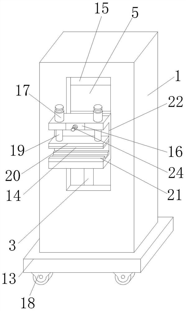
[0031] according to Figure 1-6 , a detection device for artificial intelligence experiments, comprising a detection box 1, an adjustment mechanism is fixedly installed on the inner bottom plate of the detection box 1, an adjustment plate 5 is fixedly installed on the top of the adjustment mechanism, and both sides of the adjustment plate 5 slide vertically Installed on the inner two sides of the detection box 1, the positive side plate of the detection box 1 is provided with a cavity 15, and the side of the adjustment plate 5 close to the cavity 15 is embedded with a telescopic mechanism, and the positive side end of the telescopic mechanism moves through the cavity. Cavity 15, and a clamping mechanism is fixedly installed.

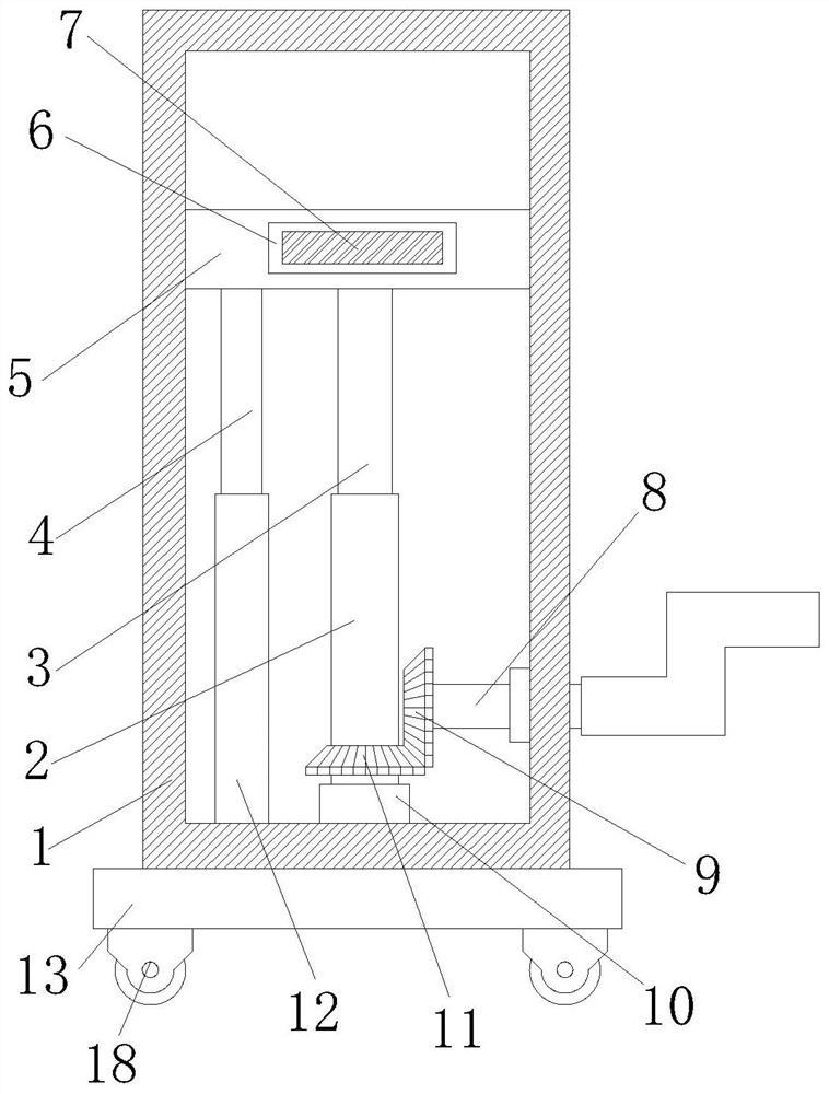
[0032] The adjustment mechanism includes a bearing 10, a second bevel gear 11, a first bevel gear 9, a rotating shaft 8, and a threaded column 3. The inner bottom plate of the detection box 1 is fixed with a bearing 10, and the top of the bearing 10 is f...

Embodiment 2

[0037] according to Figure 1-6 , a detection device for artificial intelligence experiments, comprising a detection box 1, an adjustment mechanism is fixedly installed on the inner bottom plate of the detection box 1, an adjustment plate 5 is fixedly installed on the top of the adjustment mechanism, and both sides of the adjustment plate 5 slide vertically Installed on the inner two sides of the detection box 1, the positive side plate of the detection box 1 is provided with a cavity 15, and the side of the adjustment plate 5 close to the cavity 15 is embedded with a telescopic mechanism, and the positive side end of the telescopic mechanism moves through the cavity. Cavity 15, and a clamping mechanism is fixedly installed.

[0038] The telescopic mechanism includes a telescopic tube 6, a telescopic plate 7 and a limit plate 23. A side of the adjustment plate 5 close to the cavity 15 is embedded with a telescopic tube 6. The inside of the telescopic tube 6 is horizontally sli...

Embodiment 3

[0043] according to Figure 1-6 , a detection device for artificial intelligence experiments, comprising a detection box 1, an adjustment mechanism is fixedly installed on the inner bottom plate of the detection box 1, an adjustment plate 5 is fixedly installed on the top of the adjustment mechanism, and both sides of the adjustment plate 5 slide vertically Installed on the inner two sides of the detection box 1, the positive side plate of the detection box 1 is provided with a cavity 15, and the side of the adjustment plate 5 close to the cavity 15 is embedded with a telescopic mechanism, and the positive side end of the telescopic mechanism moves through the cavity. Cavity 15, and a clamping mechanism is fixedly installed.

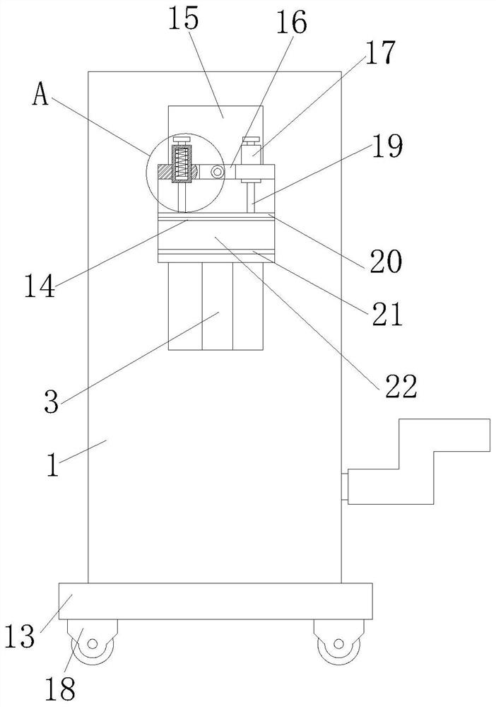
[0044] The clamping mechanism includes a clamping plate 22, a fixed plate 20, a spring plate 26, a compression spring 25, and a spring column 19. The back side of the clamping plate 22 is fixedly connected to the outer end of the telescopic plate 7, and ...


PUM


Abstract

The invention relates to the technical field of artificial intelligence, and particularly relates to a detection device for an artificial intelligence experiment. The technical problem to be solved by the invention is that manpower is wasted in a face recognition function detection mode of an existing artificial intelligence robot. In order to solve the technical problem, the detection device for the artificial intelligence experiment is mainly composed of an adjusting mechanism, a telescopic mechanism and a clamping mechanism, and a tablet computer or a mobile phone can be clamped through a restoring force of a compression spring so that an experimenter is replaced to hold the tablet computer or the mobile phone by hand, and labor is relatively saved; through the threaded sleeving relation between a threaded cylinder and a threaded column and the meshing relation between a set of bevel gears, the height of a mobile phone clamped in the clamping mechanism can be indirectly adjusted through an adjusting plate by rotating a rotating shaft, and flexiblity is achieved; and through the interference fit relation between the telescopic cylinder and the limiting plate, the telescopic length of the telescopic plate can be adjusted at will, and the telescopic plate is fixed to the corresponding position and is relatively more flexible.

Description

technical field [0001] The invention relates to the technical field of artificial intelligence, in particular to a detection device for artificial intelligence experiments. Background technique [0002] Artificial intelligence is a new technical science that studies and develops theories, methods, technologies and application systems for simulating, extending and expanding human intelligence. Among them, intelligent robots are robots based on artificial intelligence. Many robots have the function of face recognition. When the face recognition function of intelligent robots is tested experimentally, it is mainly detected by showing different photos of people in front of the robot. However, there are many problems or defects in the existing detection devices; [0003] The existing detection device mainly uses the experimenter to hold a tablet computer or mobile phone to display the photos of people in front of the artificial intelligence robot, but this method is easy to cause...

Claims


Application Information

Patent Timeline
Patent Type & Authority Applications(China)
IPC IPC(8): G01R31/00G01M99/00
CPCG01R31/00G01M99/008
Inventor 陈晓帆
Owner 上海馨盛智能科技有限公司
Why Eureka
Try Eureka