Differential pressure transmitter static pressure characteristic test and piston pressure gauge effective area verification method

A technology of differential pressure transmitter and piston pressure gauge, which is used in the measurement of fluid pressure, instruments, measuring devices, etc., can solve the problems of complex measurement process, low efficiency and long time consumption of static pressure characteristics.

Active Publication Date: 2021-09-24
中国测试技术研究院流量研究所
View PDF16 Cites 0 Cited by
  • Summary
  • Abstract
  • Description
  • Claims
  • Application Information

AI Technical Summary

Problems solved by technology

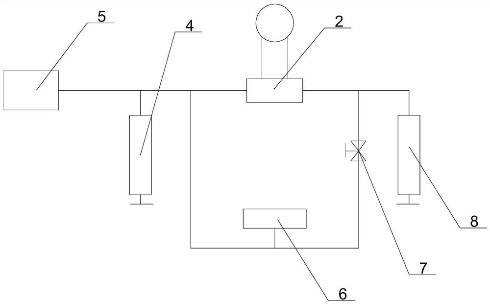
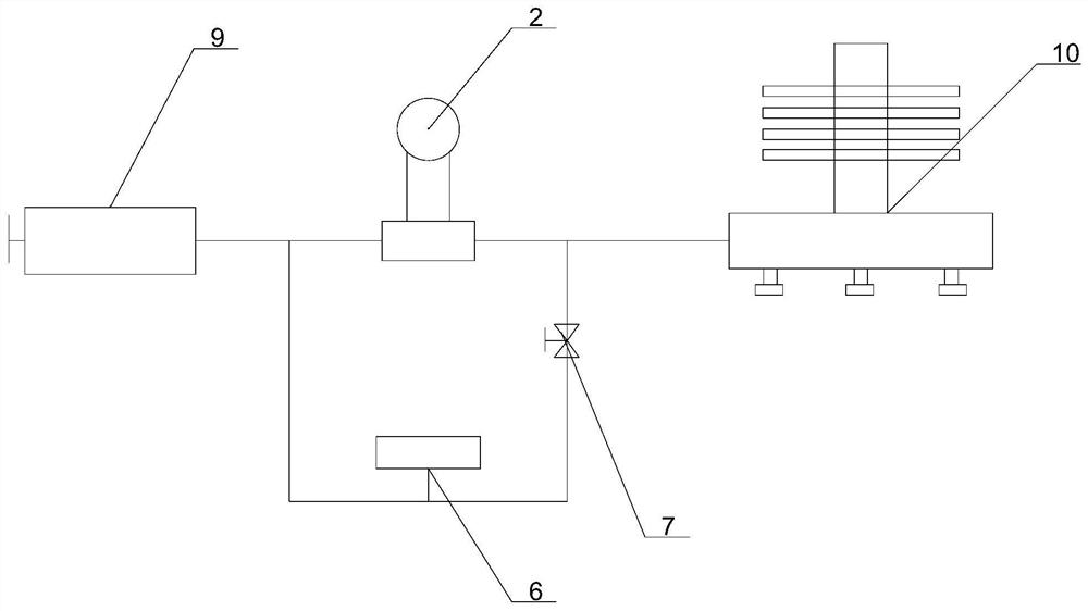
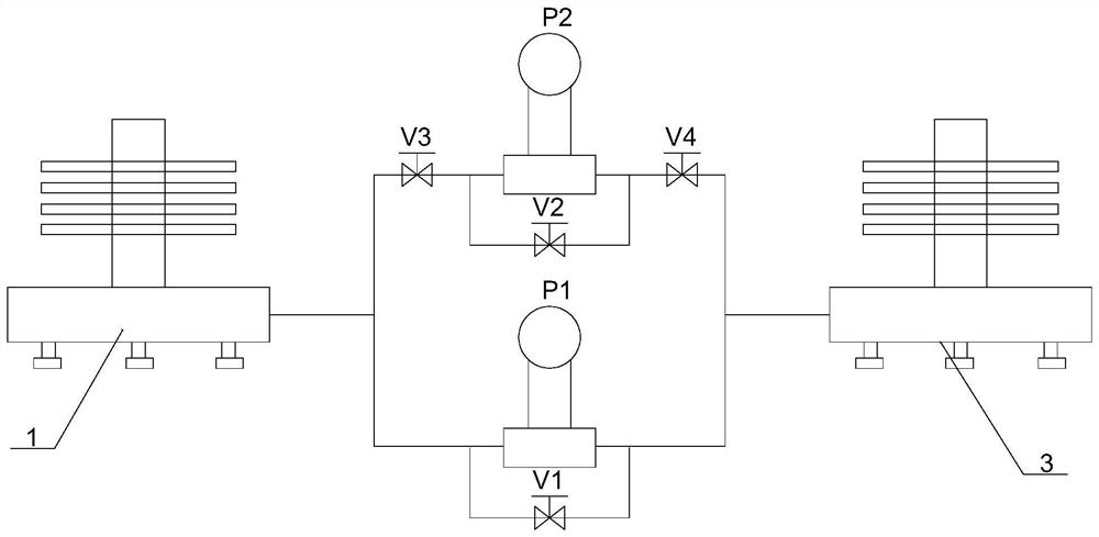
[0004] The main purpose of this application is to provide a method for testing the static pressure characteristics of a differential pressure transmitter and a method for verifying the effective area of ​​a piston pressure gauge, so as to solve the problem of relatively complicated static pressure characteristic measurement process, low efficiency and long time consumption in the related art. question

Method used


Image

  • Differential pressure transmitter static pressure characteristic test and piston pressure gauge effective area verification method
  • Differential pressure transmitter static pressure characteristic test and piston pressure gauge effective area verification method
  • Differential pressure transmitter static pressure characteristic test and piston pressure gauge effective area verification method

Examples


Embodiment Construction

[0056] In order to enable those skilled in the art to better understand the scheme of the present application, the technical scheme in the embodiments of the present application will be clearly and completely described below. Obviously, the described embodiments are only part of the embodiments of the present application, rather than Full examples. Based on the embodiments in this application, all other embodiments obtained by persons of ordinary skill in the art without creative efforts shall fall within the scope of protection of this application.

[0057] It should be noted that the terms "first" and "second" in the specification and claims of the present application are used to distinguish similar objects, but not necessarily used to describe a specific order or sequence. It should be understood that the data so used may be interchanged under appropriate circumstances for the embodiments of the application described herein.

[0058] Moreover, some of the above terms may b...


PUM


Abstract

The invention discloses a differential pressure transmitter static pressure characteristic test and piston pressure gauge transmission method. The method comprises the steps of: connecting differential pressure transmitter to a pressure source and a pressure adjusting device; connecting a pressure measuring instrument to the high-pressure end and the low-pressure end of the differential pressure transmitter in parallel; controlling the pressure source to increase the pressure to a measuring point, and recording the indicating value of the differential pressure transmitter and the indicating value P1 of the pressure measuring instrument; disconnecting the low-pressure end of the differential pressure transmitter from the pressure measuring instrument; controlling the pressure adjusting device to increase or decrease the pressure of the high-pressure end of the differential pressure transmitter, acquiring the indicating value variation of the pressure measuring instrument, and recording the indicating value Ph of the pressure measuring instrument and the indicating value [delta]P1 of the differential pressure transmitter when the variation reaches a preset upper stroke differential pressure point or lower stroke differential pressure point; and obtaining an actual differential pressure value [delta]P2 through a difference value between Ph and Pl. The problems that in the prior art, the static pressure characteristic measuring process of the differential pressure transmitter is complex, efficiency is low, and consumed time is long are solved.

Description

technical field [0001] The present application relates to the field of pressure measurement, in particular to a static pressure characteristic test of a differential pressure transmitter and a method for verifying the effective area of ​​a piston pressure gauge. Background technique [0002] Piston pressure gauge is a standard pressure measuring instrument with high accuracy, high reproducibility and high reliability based on Pascal's law and hydrostatic balance principle. It is mainly used in measurement rooms, laboratories and production or scientific experiments. Links are used as pressure references or standards. Two verification methods are provided in the piston pressure gauge verification regulations JJG59-2007 and JJG1086-2013: direct balance method and initial balance method. These two methods are also relatively recognized piston pressure measurement transmission methods in the field of pressure measurement. The initial balance method is more widely used because o...

Claims


Application Information

Patent Timeline
IPC IPC(8): G01L27/00
CPCG01L27/00G01L27/005
Inventor 甘蓉尹保来李雁灵罗凡郝罗亮
Owner 中国测试技术研究院流量研究所
Why Eureka
Try Eureka