LED driving circuit and LED lamp

A technology of LED drive and LED lamp group, applied in the direction of electrical components, etc., to avoid electromagnetic interference, reduce the requirements of pressure resistance and heat dissipation, and reduce the cost of circuit manufacturing

Active Publication Date: 2021-09-28
芯知微(上海)电子科技有限公司
View PDF13 Cites 0 Cited by
  • Summary
  • Abstract
  • Description
  • Claims
  • Application Information

AI Technical Summary

Problems solved by technology

However, when the AC voltage fluctuates or when the number of LEDs to be driven changes, the additional voltage will be on the control module, which puts forward higher requirements on the voltage resistance and heat dissipation of the control module

Method used


Image

  • LED driving circuit and LED lamp
  • LED driving circuit and LED lamp
  • LED driving circuit and LED lamp

Examples


Embodiment Construction

[0022] The present invention will be described in further detail below in conjunction with the accompanying drawings and specific embodiments. According to the following description and accompanying drawings, the advantages and characteristics of the present invention will be clearer, however, it should be noted that the concept of the technical solution of the present invention can be implemented in many different forms, and is not limited to the specific implementation set forth herein. example. The drawings are all in very simplified form and use imprecise scales, and are only used to facilitate and clearly assist the purpose of illustrating the embodiments of the present invention.

[0023] The terminology used herein is for the purpose of describing particular embodiments only and is not intended to be limiting of the invention. As used herein, the singular forms "a", "an" and "the / the" are intended to include the plural forms as well, unless the context clearly dictates...


PUM


Abstract

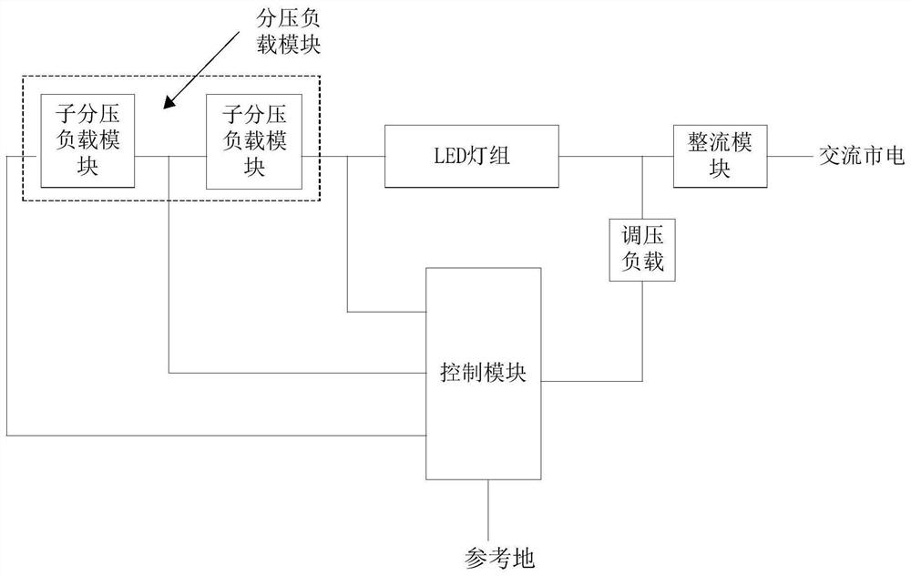
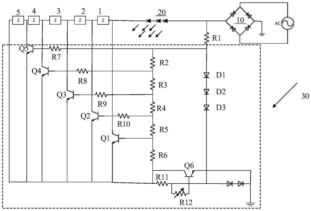
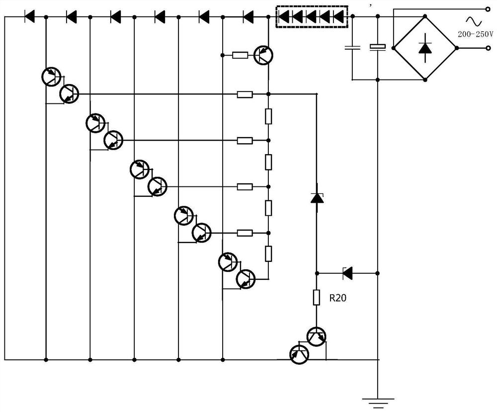
The invention provides an LED driving circuit and an LED lamp. The LED driving circuit comprises a rectification module, a voltage-dividing load module, wherein the rectification module is connected with an alternating current, carries out rectification on the alternating current, and outputs the rectified alternating current to an LED lamp bank; the voltage-dividing load module comprises a plurality of sub voltage-dividing load modules which are connected in series, and the input end of the voltage-dividing load module is connected to the output end of the LED lamp bank; the control module comprises an output end, a grounding end and a plurality of input ends, the first input end of the control module is connected to the output end of the LED lamp bank, the Nth (N is greater than or equal to 2) input end of the control module is connected to the output end of the Nth sub voltage-dividing load module along the current direction, and the output end of the control module is connected to the input end or the output end of the LED lamp bank; the control module provides constant current for the LED lamp bank and controls the number of the current output from the LED lamp bank flowing through the sub-voltage-dividing load modules when alternating voltage input into the rectification module changes, so that the current is controlled to flow into the control module from one input end, and the voltage-dividing load module is used for sharing fluctuation voltage of the LED driving circuit, so that the voltage of the control module is kept constant.

Description

technical field [0001] The invention relates to the field of LED lighting, in particular to an LED driving circuit and an LED lamp. Background technique [0002] With the advantages of high efficiency, high integration and long life, LED lamps are more and more widely used in the lighting field. The LED drive circuit converts the AC power input by the AC power supply into a constant current to drive the LED to work. In the existing LED driving scheme, the core component of the LED driving circuit is a control module, which is provided with a peripheral circuit, and the control module and the peripheral circuit cooperate to provide a constant current for the LED. The peripheral circuit includes inductors, diodes, resistors, etc., the most important of which is the inductor. The larger the inductor, the lower the operating frequency and the better the constant current effect. The existing driving circuit has the problems of complex circuit (peripheral circuit), high cost of ...

Claims


Application Information

Patent Timeline
IPC IPC(8): H05B45/345H05B45/36
CPCH05B45/345H05B45/36
Inventor 蔺光磊
Owner 芯知微(上海)电子科技有限公司
Why Eureka
Try Eureka