
Source driver and its driving method

A source driver and source driver technology, applied in the direction of instruments, static indicators, etc., can solve the problems of not being able to reach the full range of VSS~VDD, difficult Vout pull-down, etc., to achieve size reduction, circuit manufacturing cost reduction, and reduce the number of uses Effect

Inactive Publication Date: 2006-08-23
HIMAX TECH LTD
View PDF1 Cites 4 Cited by
  • Summary
  • Abstract
  • Description
  • Claims
  • Application Information

AI Technical Summary

Problems solved by technology

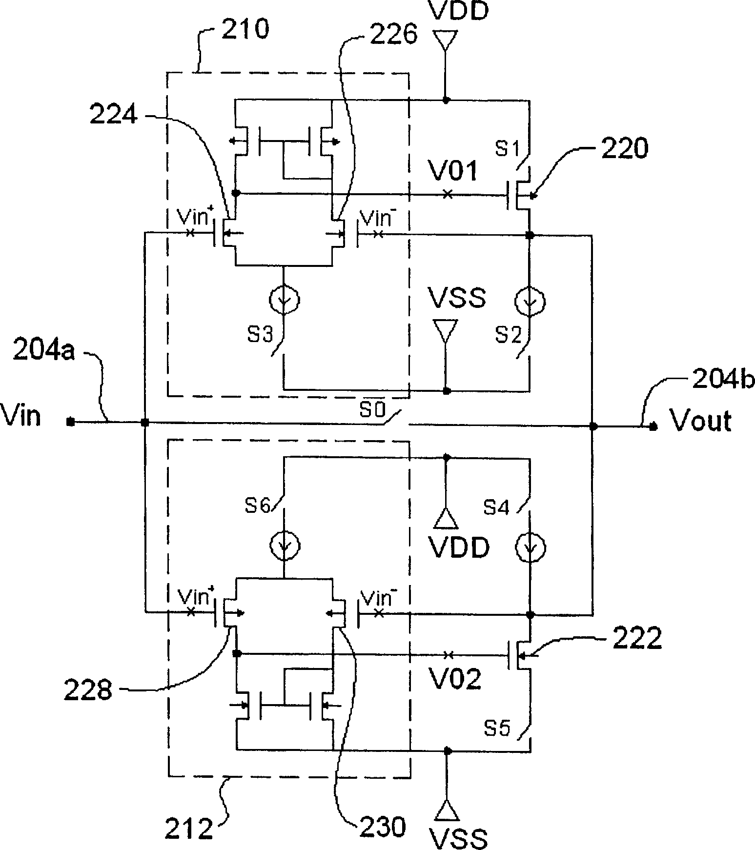
[0007] However, for the pull-up differential amplifier 210, when the output voltage Vout approaches VDD and the input level voltage Vin is greater than Vout, it is difficult for the pull-up differential amplifier 210 to continue to pull up Vout; and for the pull-down differential amplifier 212, when the output voltage Vout approaches VSS, and the input level voltage Vin is smaller than Vout, it is difficult for the pull-down differential amplifier 212 to continue to pull down Vout
Therefore, the range of the output voltage Vout of the driver 204 is limited, and cannot reach the full range of VSS~VDD

Method used


Image

  • Source driver and its driving method
  • Source driver and its driving method
  • Source driver and its driving method

Examples


Embodiment Construction

[0064] Please refer now Figure 4 , which shows a circuit block diagram of a source driver 300 of a liquid crystal display according to an embodiment of the present invention. The source driver 300 has two input terminals 300a, 300b for respectively receiving level voltage levels Vin1, Vin2 from a voltage divider (such as the voltage divider 200 shown in FIG. 2 ), and two output terminals 300c, 300d for Individually electrically connected to two data lines (such as the data line 116 shown in FIG. 1 ) of a liquid crystal panel, wherein the two output terminals 300c, 300d respectively have output voltage levels Vout1, Vout2. The source driver 300 includes a pull-up (pull high) differential amplifier 302, a pull-down (pull low) differential amplifier 304, a voltage clamping (clamp) circuit 306, a first switch circuit 308, a second switch circuit 310 and a third switch circuit 312 . The first switch circuit 308 has switches S1 , S2 , S3 and S4 ; the second switch circuit 310 has ...


PUM


Abstract

This invention relates to a source driver of a LCD used in driving a data line containing an input used in receiving a preset voltage quasi-potential, an output end connected to said data line and having an output voltage quasi-potential, a voltage control circuit used in controlling the output voltage potential in a preset sphere, a first differential amplifier used in increasing said controlled output voltage quasi-potential to that of said preset voltage and a second differential amplifier used in reducing said controlled output quasi-potential to that of the preset one. A method for source driving is provided.

Description

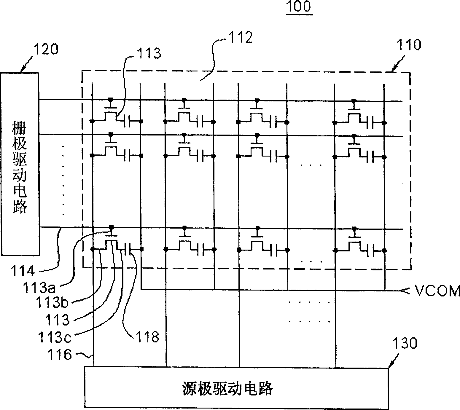
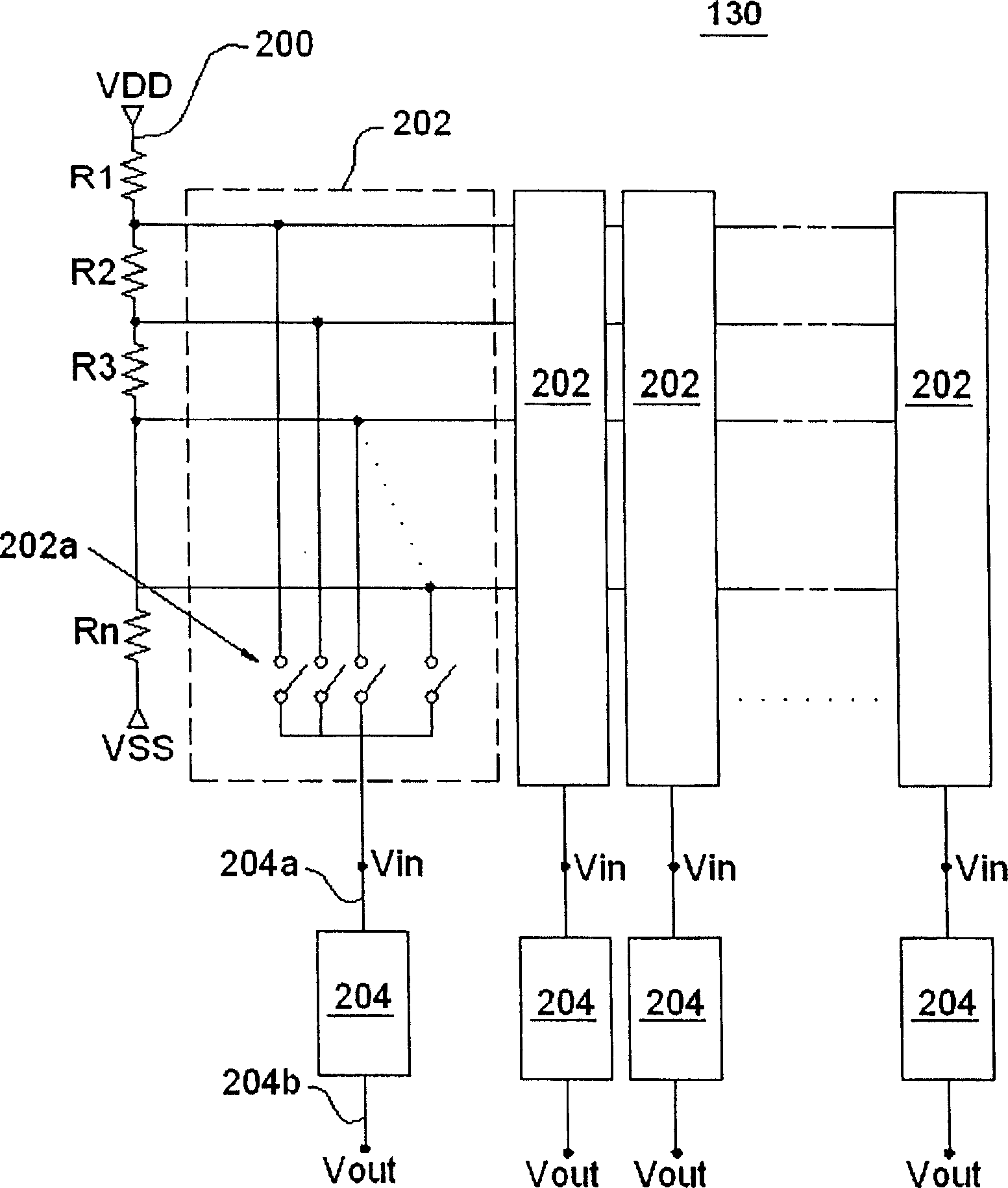
technical field [0001] The present invention relates to a source driver and its driving method, more particularly to a source driver of a liquid crystal display and its driving method. Background technique [0002] FIG. 1 is a schematic diagram of a driving circuit of a known active matrix liquid crystal display device 100 . The liquid crystal display device 100 includes a liquid crystal panel 110 on which a thin film transistor array 112 , a gate driving circuit 120 and a source driving circuit 130 are disposed. The thin film transistor array 112 is composed of a plurality of thin film transistors 113 . The gate 113 a of each TFT 113 is connected to a corresponding scan line 114 , the source 113 b is connected to a corresponding data line 116 , and the drain 113 c is connected to one terminal of a corresponding display capacitor 118 . The other end of each display capacitor 118 is connected to a common voltage VCOM. The gate driving circuit 120 is used for providing swit...

Claims


Application Information

Patent Timeline
IPC IPC(8): G09G3/36G02F1/133
Inventor 张耀光邱明正
Owner HIMAX TECH LTD
Learn More