Laser power meter

A laser power meter and absorber technology, applied in the field of laser radiation parameter measurement, can solve the problems of uneven distribution of laser power density, prone to temperature drift, slow response of power meter, etc., to improve laser damage threshold and reduce laser power density , the effect of improving the response speed

Pending Publication Date: 2021-11-02
四川激束光电仪器有限公司
View PDF0 Cites 2 Cited by
  • Summary
  • Abstract
  • Description
  • Claims
  • Application Information

AI Technical Summary

Problems solved by technology

Current high-power laser power meters generally use calorimetry to measure laser power, but they cannot meet the current high-power laser measurement requirements in terms of measurement accuracy, response speed and laser damage resistance.
This is because, on the one hand, most of the existing laser power meters measure the surface temperature of the absorber rather than the internal temperature, so the temperature measurement error is relatively large, and temperature drift is easy to occur
In addition, the existing laser power meter has a large thermal resistance during the heat conduction process, the thermal equilibrium time is long, and the power meter responds slowly
In addition, the existing laser power meter has relatively low beam expansion of the incident laser, and the distribution of laser power density on the absorption surface is uneven, resulting in poor resistance to laser damage, and the probability of being damaged by the laser during the measurement process is very high

Method used


Image

  • Laser power meter
  • Laser power meter
  • Laser power meter

Examples


Embodiment Construction

[0022] The present invention will be described in detail below in conjunction with the embodiments in the accompanying drawings.

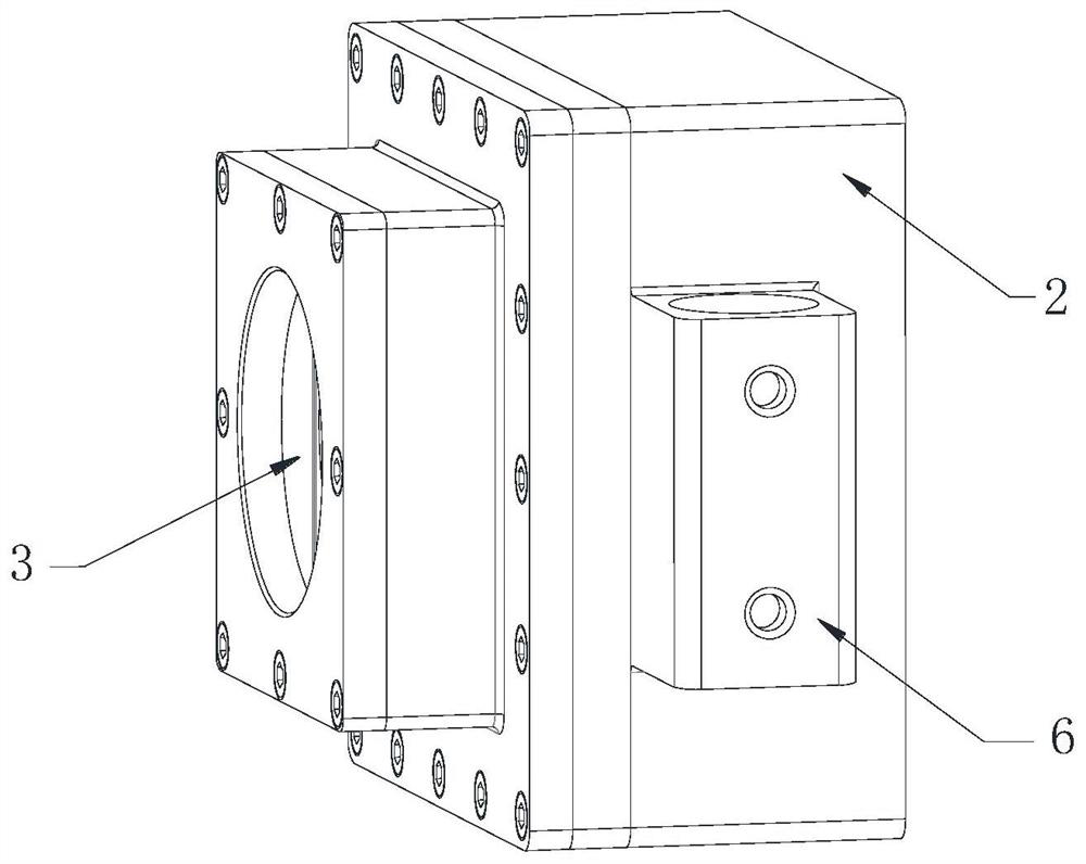
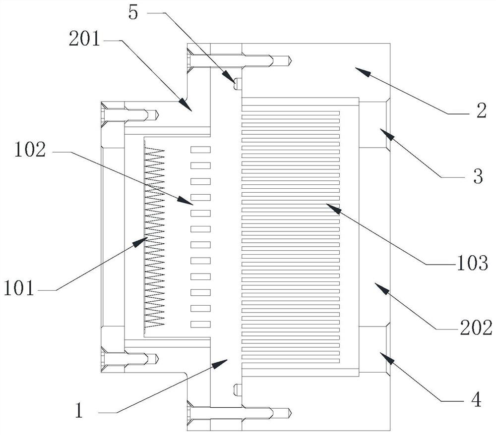
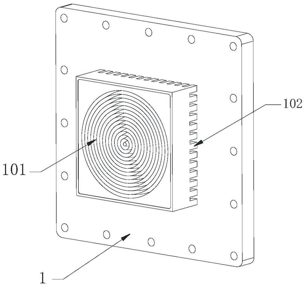
[0023] refer to Figure 1~4 As shown, a laser power meter in this embodiment mainly includes an absorber 1 and a housing 2 . The absorber 1 is placed inside the shell 2, and the two are fixed together by screws.

[0024] The absorber 1 is the core component of the laser power meter, which is made of a whole piece of pure copper, and includes key functional modules such as the absorbing target surface 101 , the flow guide component 102 and the heat dissipation component 103 .

[0025] The front end of the absorber 1 is an absorbing target surface 101 for absorbing the energy of incident laser light and converting it into heat energy. In order to improve the absorption rate of incident laser light, the absorption target surface 101 is processed into a V-shaped annular groove structure with a sharp bottom, and a surface treatment process is adopted ...


PUM


Abstract

The invention discloses a laser power meter which mainly comprises an absorber and a shell; wherein the core part is an absorber which is formed by processing a whole block of high-thermal-conductivity material and comprises an absorption target surface, a flow guide assembly, a heat dissipation assembly and the like. The absorption target surface is right opposite to the laser incident port of the shell, and the target surface comprises a series of concentric V-shaped circular ring grooves and is used for improving the absorptivity of incident laser. The flow guide assembly comprises a flow guide column array, and temperature sensors are installed at the two ends of holes between flow guide columns respectively and can measure the temperature of the hot end and the cold end in the absorber, and thereby the power of the laser to be measured can be calculated according to the measured temperature difference. The heat dissipation assembly is arranged in a running water environment so as to improve the heat dissipation efficiency. A water inlet and a water outlet are formed in the shell and connected with external cooling water to achieve water-cooling heat dissipation. The laser power meter adopts an integrated absorber design, so that the heat balance time can be shortened, and the response speed can be improved. Meanwhile, the laser absorptivity of the absorption target surface is high, and the measurement result is more accurate and stable.

Description

technical field [0001] The invention belongs to the technical field of laser radiation parameter measurement, and relates to a laser power measurement device, in particular to a high-power laser power meter. Background technique [0002] In recent years, high-power laser technology has become increasingly mature and widely used in various fields. In this process, the output power of lasers has been continuously improved. For example, the fastest-growing fiber laser in recent years, the output power of a single module has reached more than 10,000 watts, and the output power of multi-mode lasers has exceeded 100kW. With the increase of laser power level, corresponding laser power measurement equipment needs to be equipped for performance monitoring and evaluation. Current high-power laser power meters generally use calorimetry to measure laser power, but they cannot meet the current high-power laser measurement requirements in terms of measurement accuracy, response speed and...

Claims


Application Information

Patent Timeline
Patent Type & Authority Applications(China)
IPC IPC(8): G01K17/00
CPCG01K17/003
Inventor 徐德于靖冉铮惠丁宇洁
Owner 四川激束光电仪器有限公司
Why Eureka
Try Eureka