

Two-stage air suspension centrifugal compressor capable of reducing radial force
A centrifugal compressor and air suspension technology, applied in the field of compressors, can solve the problems of reducing the quality of compressed gas, turbulent air flow, inability to separate, etc., to improve the life and stability, improve the quality of compressed gas, and uniform radial force. Effect
- Summary
- Abstract
- Description
- Claims
- Application Information
AI Technical Summary
Problems solved by technology
Method used
Image

Examples
Embodiment 1
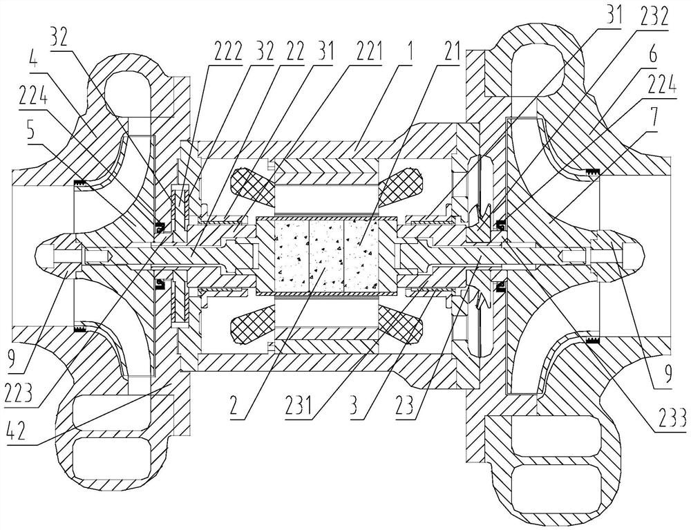
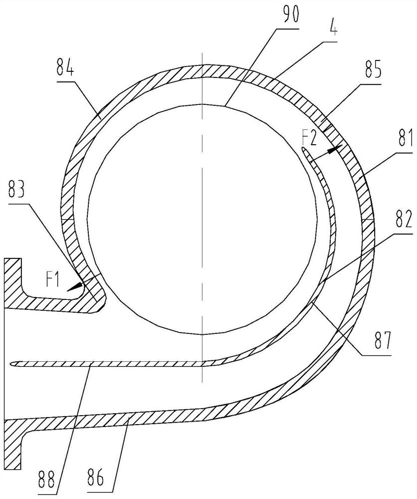
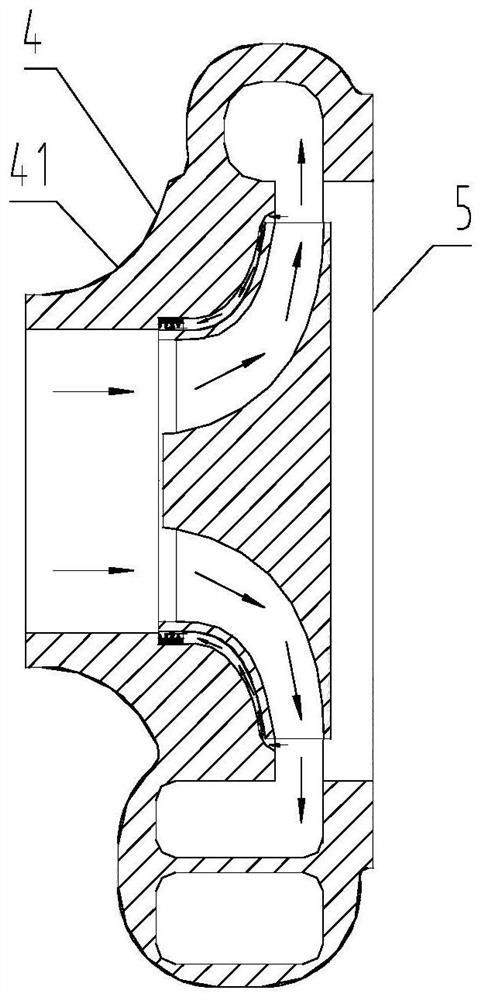
[0026] Such as figure 1 , figure 2 Shown is a two-stage air suspension centrifugal compressor with reduced radial force, the compressor includes a motor casing 1, a motor shaft 2, an air bearing device 3, a first volute 4, a first impeller 5, a second volute The shell 6 and the second impeller 7; the air bearing device 3 is sleeved on the outer wall of the motor shaft 2, and the first impeller 5 and the second impeller 7 are respectively fixed on both ends of the motor shaft 2 and are respectively located in the first volute 4 and the second volute 6; the first volute 4 and the second volute 6 both include a volute body 81 and a partition 82, and the partition 82 is fixedly arranged in the cavity inside the volute body 81; the volute body 81 is provided with a partition tongue 83, The first helical section 84, the second helical section 85 and the diffusion section 86, the first helical section 84 starts from the partition tongue 83, and ends at the intersection of the diame...
PUM
 Abstract
Description
Claims
Application Information