Screen projection device for multimedia teaching
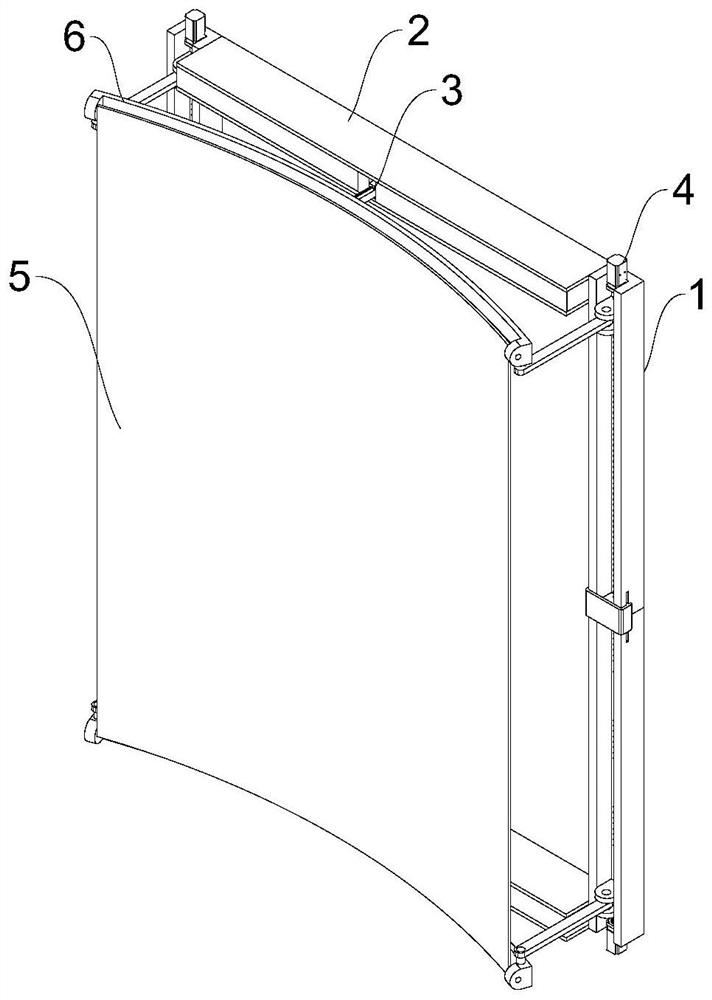
A technology for multimedia teaching and screen projection, applied in projection devices, educational appliances, optics, etc., can solve the problems of folded and damaged curtains, difficulty in controlling the unfolding effect, etc., achieve the effect of easy unfolding arc and improve the effect of video viewing
- Summary
- Abstract
- Description
- Claims
- Application Information
AI Technical Summary
Problems solved by technology
Method used
Image
Examples
Embodiment 1
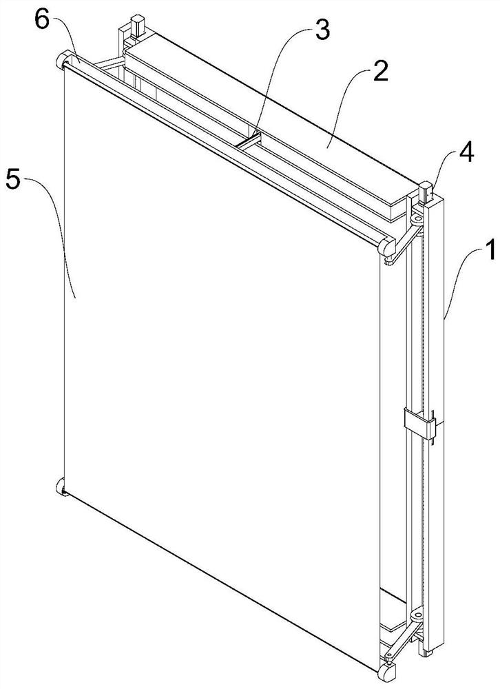
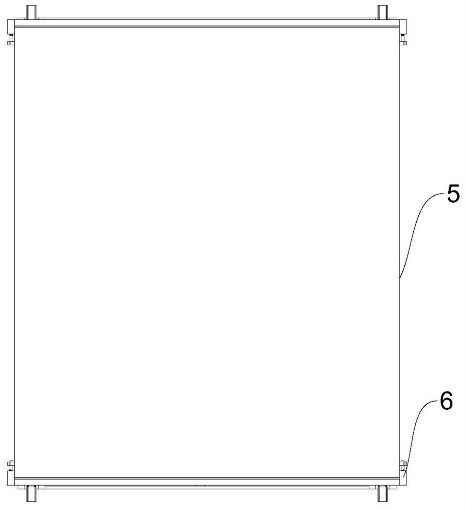
[0027] see Figure 1-3 A screen projection device for multimedia teaching, comprising a screen projection bracket and a curtain 5; the screen projection bracket includes a support rod 1, a support beam 2, a curtain adjustment mechanism 3, a lifting control mechanism 4, four support rods 1 and two support beams 2 are enclosed to form a projection screen bracket, the screen adjustment mechanism 3 is installed inside the support beam 2, the lifting control mechanism 4 is arranged inside the support rod 1, and the upper and lower ends of the screen 5 are symmetrically fixed with elastic connecting rods 6.
[0028] The two support beams 2 are arranged horizontally and have a vertically symmetrical structure. The upper and lower support beams 2 are arranged in a vertically symmetrical structure and are connected by hinges.
[0029] The present invention provides a screen projection device for multimedia teaching, which improves the screen projection support connected to the screen 5...
Embodiment 2
[0032] see Figure 4 , 6 , 7, based on Embodiment 1, the difference is that the curtain adjustment mechanism 3 includes a fixed plate 301, the support beam 2 is a rectangular hollow structure, the fixed plate 301 is fixed at the middle position inside the support beam 2, and the right end surface of the fixed plate 301 A chute 302 with opening to the right is fixed, and a slide bar 303 is slidably connected inside the chute 302. The slide bar 303 passes through the support beam 2 forward and extends to its front side and is slidably connected with it. The rear end of the slide bar 303 is fixed with a rotating seat 304, the upper and lower ends of the chute 302 are symmetrically fixed to the front side with fixed rods 305.
[0033] The curtain adjustment mechanism 3 includes a cylinder 306, which is arranged on the right side of the fixed plate 301, the right end of the cylinder 306 vertically runs through the rotating shaft A307, and the rotating shaft A307 extends to the inn...
Embodiment 3
[0038] see Figure 4 , 6 , based on Embodiment 1-2, the difference lies in that the lifting control mechanism 4 includes a threaded rod A401, the front end of the support rod 1 is vertically provided with a rectangular groove 402, and the threaded rod A401 is vertically arranged inside the rectangular groove 402 Realize the rotation connection, the threaded rod A401 is connected with the servo motor 403 at the non-threaded part of the outer end, the sliding seat 404 is slid inside the rectangular groove 402, the threaded rod A401 runs through the sliding seat 404 and is connected to it in rotation, and the front end of the sliding seat 404 is connected with a rotating connection Rod A405, the front end of connecting rod A405 is connected with threaded rod B406, and the two support rods 1 are symmetrically provided with limit grooves A407 on the sides where they are close to each other, and a U-shaped slider 408 is arranged on the front side of one of the The block 408 is rest...
PUM
 Abstract
Description
Claims
Application Information
 - R&D
- Intellectual Property
- Life Sciences
- Materials
- Tech Scout
- Unparalleled Data Quality
- Higher Quality Content
- 60% Fewer Hallucinations
Browse by: Latest US Patents, China's latest patents, Technical Efficacy Thesaurus, Application Domain, Technology Topic, Popular Technical Reports.
© 2025 PatSnap. All rights reserved.Legal|Privacy policy|Modern Slavery Act Transparency Statement|Sitemap|About US| Contact US: help@patsnap.com


