Method for improving halo effect of display

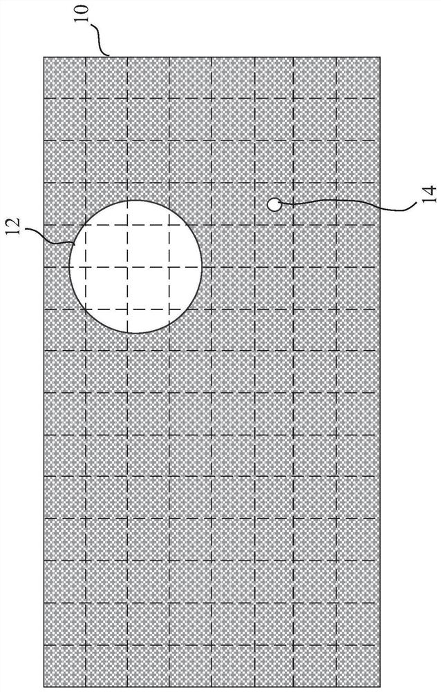
A display and effect technology, applied in the direction of static indicators, instruments, etc., can solve the problems of image quality degradation in bright area 12, reduce brightness of bright area 12, etc., and achieve the effect of suppressing halo effect

Pending Publication Date: 2021-11-19
ELAN MICROELECTRONICS CORPORATION
View PDF13 Cites 0 Cited by
  • Summary
  • Abstract
  • Description
  • Claims
  • Application Information

AI Technical Summary

Problems solved by technology

However, in the case of a large-area bright area 12 and a small-area bright area 14 at the same time, the traditional method will r

Method used


Image

  • Method for improving halo effect of display
  • Method for improving halo effect of display
  • Method for improving halo effect of display

Examples


Embodiment Construction

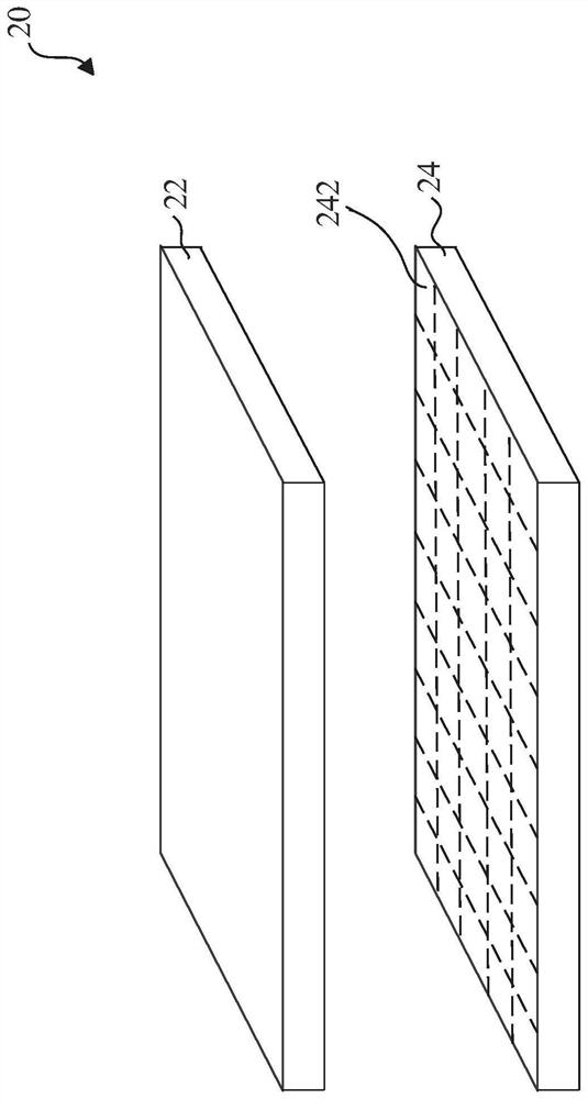
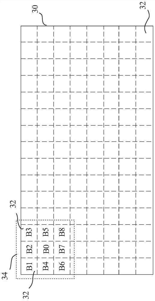
[0016] figure 2 Application of the method of the present invention display monitor 20. Display 20 comprises a display panel 22 and a backlight 24. The display panel 22 for displaying images. The backlight panel 24 is located below the display panel 22 and having a plurality of light emitting regions 242, each light emitting region 242 comprises one or more light emitting elements (not shown), such as light emitting diodes. A brightness of each light emitting region 242 can be independently controlled, so that the luminance of the plurality of light-emitting regions 242 may be different. image 3 Display 30 for displaying the image display 20, image 30 may be divided into a plurality of sub-regions 32 corresponding to the plurality of light emitting regions 242, respectively, each sub-region 32 comprises a plurality of pixels.

[0017] Figure 4 The method of improving a display halo effect of the present invention. Refer image 3 and Figure 4 , Step S10 is first carried out to dete...


PUM


Abstract

A method for improving halation effect of a display is provided, the display is used for displaying an image and comprises a backlight plate, the image comprises a plurality of sub-regions, and the backlight plate is provided with a plurality of light-emitting regions respectively corresponding to the plurality of sub-regions. The method comprises the following steps of: determining brightness information of each sub-region; selecting one sub-region as a target region, and determining a correction value according to the maximum value of the brightness information of other sub-regions adjacent to the target region; and adjusting the brightness of the light-emitting area corresponding to the target area according to the correction value.

Description

Technical field [0001] The present invention relates to a method for improved display halo effect. Background technique [0002] A display system having a local dimming (local dimming system) is displayed in a dark scene image (dark-scene image), the light leakage generated by a halo effect (halo effect) may occur in the black pixel. Please refer to figure 1 , figure 1 A plurality of light emitting regions of the backlight sub-Videos dotted line. like figure 1 , When the display shows a dark scene image 10, if a large area of ​​the bright region 12 occurs, a halo effect imperceptible to the human eye. However, when a dark scene image 10 appears in a small area of ​​the bright region 14, the human eye will see the edge of the bright area 14 of halos. Especially in a dark environment, the halo effect will be more obvious. Traditional method of suppressing a halo effect is the overall luminance of the backlight is lowered. However, while a large area of ​​the bright region 12 and a ...

Claims


Application Information

Patent Timeline
IPC IPC(8): G09G3/34
CPCG09G3/3426
Inventor 谢坤霖陈翰纬林嘉兴
Owner ELAN MICROELECTRONICS CORPORATION
Why Eureka
Try Eureka