
Light source module

A technology for light source modules and light-emitting elements, which is applied in the directions of light guides, optics, and optical elements, and can solve the problems of blurring and falling edges of displayed images.

Pending Publication Date: 2021-07-06
CORETRONIC
View PDF13 Cites 0 Cited by
  • Summary
  • Abstract
  • Description
  • Claims
  • Application Information

AI Technical Summary

Problems solved by technology

Therefore, a halo effect will appear around the light-emitting area of ​​the LED, which will cause the edges of the displayed image to become blurred, resulting in a decrease in the overall display quality (eg, display contrast)

Method used


Image

  • Light source module
  • Light source module
  • Light source module

Examples


Embodiment Construction

[0020] In the following detailed description of the preferred embodiments, reference is made to the accompanying drawings which form a part hereof, and in which are shown by way of illustrations specific embodiments in which the invention may be practiced. In this regard, directional terms such as "top", "bottom", "forward", "rearward", etc. are used with reference to the orientation of the various figures described. The components of the present invention can be positioned in several different orientations. Accordingly, the directional terms are used for illustration and not for limitation. On the other hand, the drawings are merely schematic and the size of elements may be exaggerated for clarity. It is to be understood that other embodiments may be utilized and structural changes may be made without departing from the scope of the present invention. Also, it is to be understood that the phrases and terms used herein are for the purpose of description and should not be reg...


PUM


Abstract

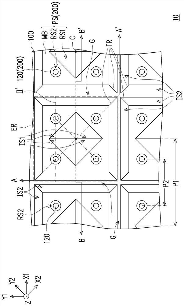
The invention provides a light source module comprising a substrate and a plurality of light-emitting units. The light-emitting units are arranged on the surface of the substrate, and each light-emitting unit comprises a first light-emitting element, a second light-emitting element, a first reflecting element, a second reflecting element and a packaging structure. The packaging structure comprises a main body part and a first groove. The main body portion covers the first light-emitting element and the second light-emitting element. According to the light source module, the light emitting uniformity of the light source module can be improved.

Description

technical field [0001] The present invention relates to a backlight module, and in particular to a light source module. Background technique [0002] With more and more applications of non-self-illuminating displays (for example, liquid crystal displays), the design of the backlight module also needs to be adjusted for different applications. In order to meet the requirements of large-size, high dynamic range (HDR) and high-contrast displays, the backlight module needs to have a local dimming function. Therefore, the direct-lit type backlight module using light-emitting diodes as the main light source has gradually become the mainstream of the market. Since the total thickness of this type of backlight module is thin (for example, the light distance is less than 10 mm), the LEDs are usually covered by a packaging layer with a light-emitting structure to achieve a more uniform light-emitting effect on the light-emitting surface of the backlight module. However, when the lig...

Claims


Application Information

Patent Timeline
Patent Type & Authority Applications(China)
IPC IPC(8): G02F1/13357G09F9/00
CPCG02F1/133602G02F1/133605G02F1/133608G02F1/133603G09F9/00H01L25/0753H01L33/60H01L33/54G02B6/0036
Inventor 林士逸杨文勋黄于铵
Owner CORETRONIC
Learn More