Bendable solid state planar light source structure, flexible substrate therefor, and manufacturing method thereof

a solid-state planar light source and flexible technology, applied in the direction of light source semiconductor devices, fixed installations, lighting and heating apparatus, etc., can solve the problems of reducing the forward light-emitting efficiency of the ssl, poor heat dissipation, and accelerated failure of the ssl element, and achieve the desired heat sink effect, high light-emitting efficiency, and preferred photoelectric characteristics

Active Publication Date: 2007-09-20
IND TECH RES INST
View PDF8 Cites 37 Cited by
  • Summary
  • Abstract
  • Description
  • Claims
  • Application Information

AI Technical Summary

Benefits of technology

[0010]The present invention provides a bendable solid state lighting (SSL), wherein an SSL wafer is cut into small dies, and the dies are directly bonded with a bendable metal sub-mount that has a circuit, such that the SSL array has a desirable heat sink effect, preferred photoelectric characteristics, and relatively high light-emitting efficiency.
[0011]In an embodiment of the present invention, a bendable LED planar light source structure is provided, which comprises a flexible substrate with metal layers on both sides, wherein the metal layer on one side has a circuit layout, and the metal layer on the other side has a pattern structure or as a whole metal coating with reflecting and scattering characteristics, which effectively improves the light uniformity, light emitting intensity and efficiency of the planar light source. Meanwhile, bonding pads are provided on the same side or opposite side as the metal layer with the circuit layout, and an array of a plurality of LED dies is bonded with the bonding pads through wire bonding or flip chip bonding, such that the LED dies are conducted with current through the circuit layout on the flexible substrate, so as to form a planar light source.
[0012]In an embodiment of the present invention, a bendable light source is provided, which includes a flexible substrate and a plurality of light emitting diode (LED) dies. The flexible substrate has a first metal layer and a second metal layer, wherein the first metal layer has a circuit layout, and the second metal layer, formed on the flexible substrate, has a pattern structure or as a whole metal coating with reflecting and scattering characteristics, which efficiently improves the light uniformity and the light-emitting intensity and efficiency of the planar light source. In addition to the plurality of structure regions, the above mentioned structure region also has a plurality of bonding pads electrically connected to the first metal layer. The LED dies are disposed on the structure region in an array, and are bonded with the corresponding bonding pads, such that the LED dies are conducted with current via the circuit layout of the first metal layer on the flexible substrate, so as to form a planar light source.
[0016]The second metal layer provided on the flexible substrate is a metal coating with a high reflectivity, so as to enhance the forward light-emitting efficiency of the LED die, and also reduce the ratio between the light intensity at axial area of the LED die and that at surrounding area of the LED die, thus improving the light uniformity of the planar light source.

Problems solved by technology

Currently, there are many difficulties when applying the feature of bendability to SSL, for example, first, SSL dies are made of rigid and friable materials and cannot be bent.
Next, when the SSL is applied in the back light module, the SSL lamp is jointed with a substrate having a large area, such that heat dissipation is poor, and failure of the SSL element is accelerated.
Further, the SSL substrate itself has the effect of light-absorbing, such that the forward light-emitting efficiency of the SSL is reduced.
Since the SSL chip is a non-directional light source, the forward emitted light of the SSL Chip is rather limited, and with the additional absorption effect of the substrate, the internal absorption loss of the SSL becomes excessively large, thus, the external light extraction efficiency is relatively low.
However, using the large-scaled (≧40 mil) SSL dies results in problems of poor current distribution and poor light-emitting efficiency due to the heat accumulation.
However, the heat dissipation effect is also limited.
The Luxeon SSL back light module provides a preferred amount of emitted light, however, since it includes SSL dies of more than 40 mils in size, the heat dissipation is poor, and the module is also not bendable.
When the SSL is applied in a back light module, the SSL lamps are jointed with a large-sized substrate, such that the heat dissipation is poor, and failure of the SSL elements is accelerated.
However, the heat sink effect of the light source module 300 is restricted to the heat sink effect achieved at the segmented heat sink tracks on the same side, and a metal frame is also required, which makes a limited contribution to improving the heat sink effect, except for achieving an aesthetic appearance.

Method used


Image

  • Bendable solid state planar light source structure, flexible substrate therefor, and manufacturing method thereof
  • Bendable solid state planar light source structure, flexible substrate therefor, and manufacturing method thereof
  • Bendable solid state planar light source structure, flexible substrate therefor, and manufacturing method thereof

Examples


Embodiment Construction

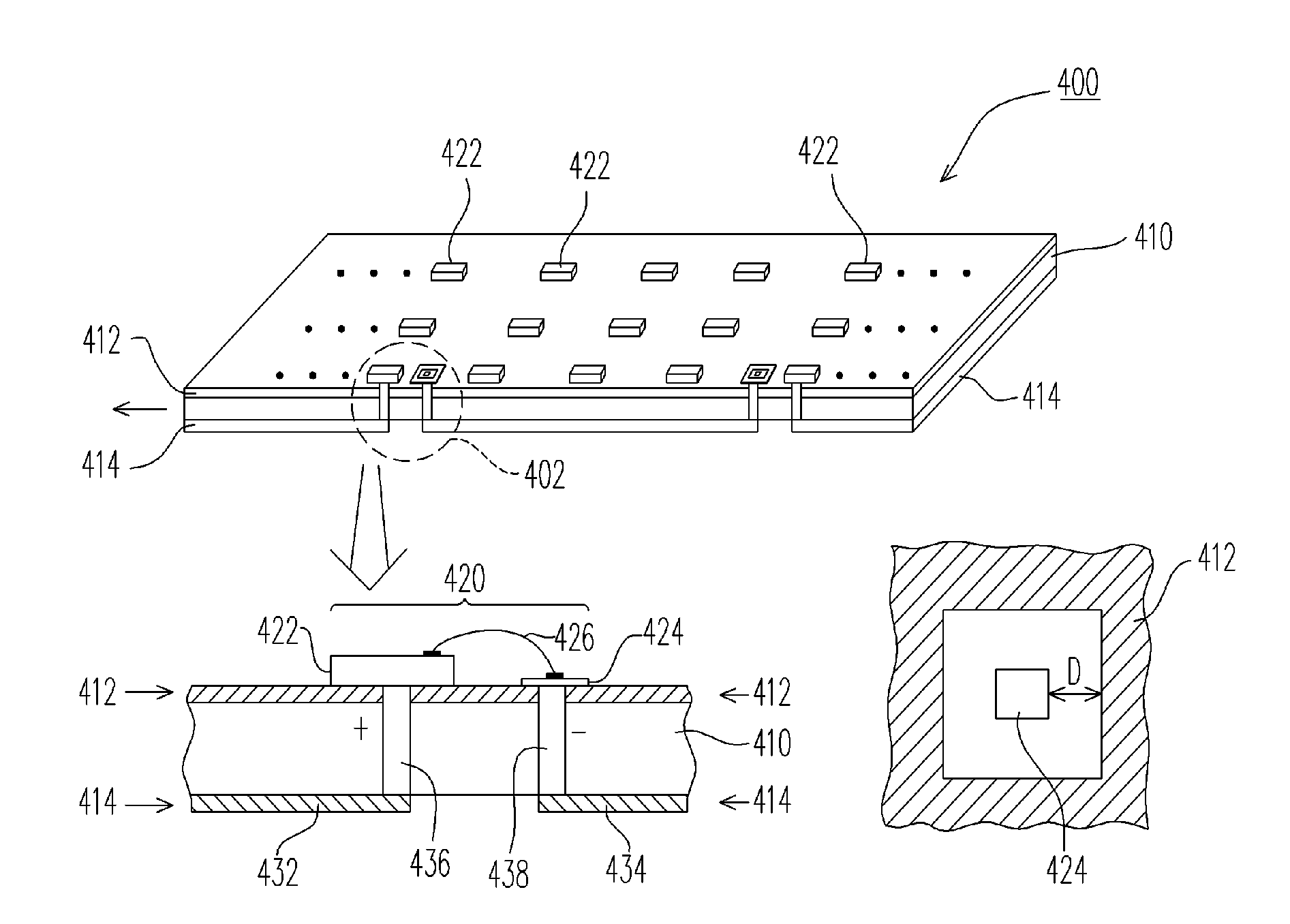
[0032]The present invention provides a bendable solid state lighting (SSL), wherein the SSL wafer is cut into small dies, and the dies are directly bonded with a bendable metal sub-mount having a circuit, such that the SSL array has desirable thermal conductivity, preferred photoelectric characteristics, and relatively high light-emitting efficiency.

[0033]Conventionally, the high power SSLs are generally manufactured into those with a large size, i.e., larger than 40 mils, thus resulting in a problem of poor current distribution, and poor light-emitting efficiency due to the heat accumulation. In order to solve the above problem, the present invention provides a bendable solid state light source, in which the thinned wafer is cut into small dies, i.e., less than 40 mils, and a size of less than or equal to 25 mils also can be used in an embodiment, or preferably between 8 mils and 14 mils in a preferred embodiment. The thinned small dies are directly bonded with the bendable metal s...


PUM


Abstract

A bendable LED planar light source structure, a flexible substrate therefore, and a manufacturing method thereof are provided. The flexible substrate has metal layers on both sides, where the metal layer on one side has a circuit layout, and the metal layer on the other side has a pattern structure or a whole metal coating with reflecting and scattering characteristics. Meanwhile, bonding pads are provided on the same side or opposite side as the metal layer with the circuit layout, and an array of LED dies is bonded with the bonding pads through wire bonding or flip chip bonding, such that the LED dies are conducted with current through the circuit layout on the flexible substrate, so as to form a planar light source.

Description

CROSS-REFERENCE TO RELATED APPLICATION[0001]This application claims the priority benefit of Taiwan application serial no. 95109119, filed on Mar. 17, 2006. All disclosure of the Taiwan application is incorporated herein by reference.BACKGROUND OF THE INVENTION[0002]1. Field of Invention[0003]The present invention relates to an solid state planar light source structure, and more particularly, to a bendable LED planar light source structure, a flexible structure and a manufacturing method thereof, which is directly bonded with a bendable metal sub-mount having a circuit, so as to enhance the thermal conduction effect, thereby achieving preferable photoelectric characteristics and higher light-emitting efficiency.[0004]2. Description of Related Art[0005]Solid state lighting (SSL) is a micro solid state light source having the advantages of desired shock resistance, power saving, long life-span, and diversified and pure colors, which meets various application demands and has gradually b...

Claims


Application Information

Patent Timeline
Patent Type & Authority Applications(United States)
IPC IPC(8): F21S8/00F21K99/00
CPCF21K9/00F21V33/0008H05K1/0203H05K1/189H05K2201/09318H05K2201/09481H05K2201/10106H01L2924/0002H05K2201/10553H05K2203/049F21Y2105/001H01L2924/00F21Y2105/10F21Y2115/10
Inventor YANG, CHIEN-CHENGHSU, CHAO-KAICHANG, JING-YAO
Owner IND TECH RES INST
Why Eureka
Try Eureka