Illumination apparatus

a technology of illumination apparatus and illumination area, which is applied in the direction of lighting and heating apparatus, printing, instruments, etc., can solve the problems of insufficient luminance uniformity, inconvenient use, and insufficient luminance so as to achieve the effect of improving the uniformity of light out of light-guiding modules

Inactive Publication Date: 2012-01-19
QISDA CORP
View PDF3 Cites 44 Cited by
  • Summary
  • Abstract
  • Description
  • Claims
  • Application Information

AI Technical Summary

Benefits of technology

[0010]Compared with the prior art, the illumination apparatus according to the invention uses the light-emitting devices disposed in annular arrangement to produce a radially light-guiding structure and further controls the disposition density of the light-emitting devices and the reflection light energy of the reflection structure produced by the light-guiding module so as easily to obtain uniform light out the light-guiding module. Even though the profile of the light-guiding module is irregular, the uniformity of the light out the light-guiding module is still improved effectively.

Problems solved by technology

To an LED illumination apparatus with a single point source, its luminance and illumination area are too limited to be illumination for reading; the bright spot due to the point source makes eyes of a user uncomfortable.
This configuration is conducive to increasing the luminance and expanding the illumination area; however, the luminance uniformity is still insufficient.
However, in this case, its circuit structure is easily too large to maintain; besides, if the LED is high power, it is not conducive to the design for its heat-dissipating structure.
Furthermore, for different-sized light-guiding plates, the structure details need to be designed respectively, which is quite unfavorable to production design and manufacturing.

Method used


Image

  • Illumination apparatus
  • Illumination apparatus
  • Illumination apparatus

Examples


Embodiment Construction

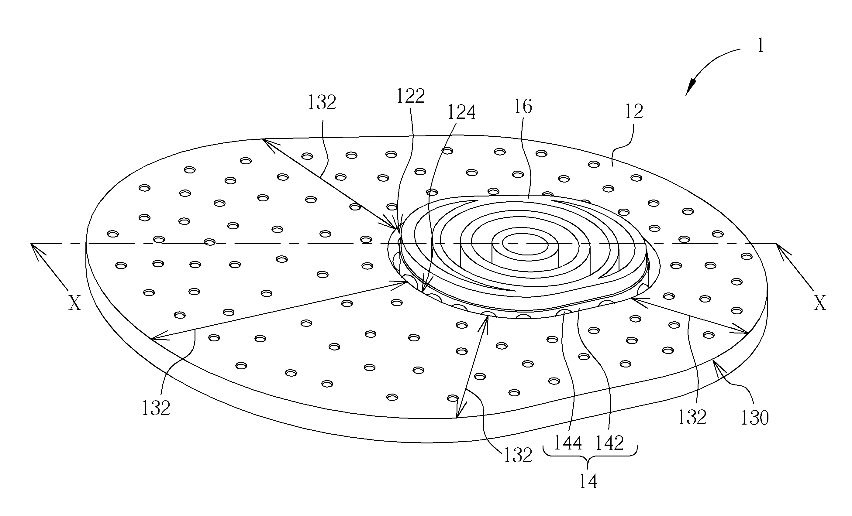
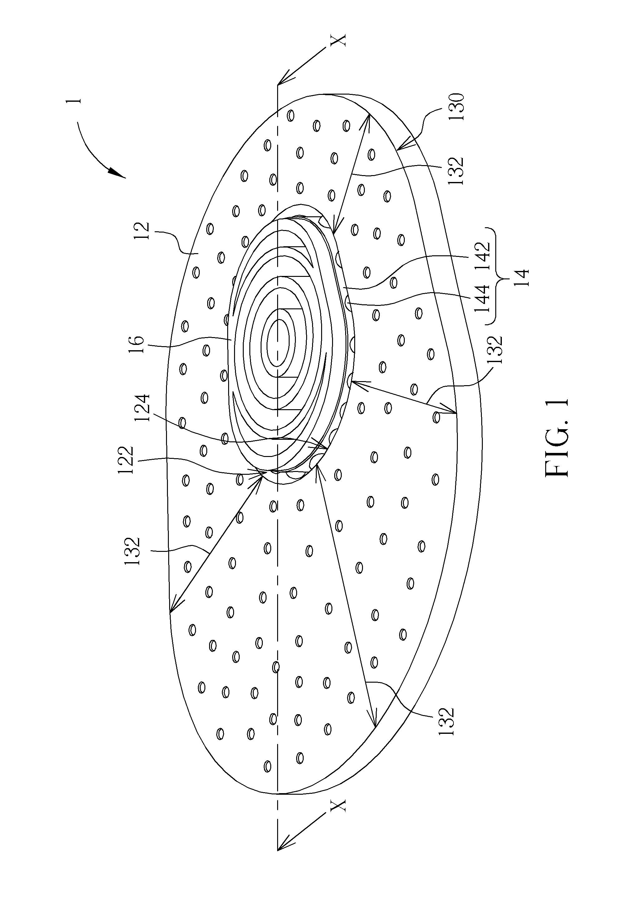
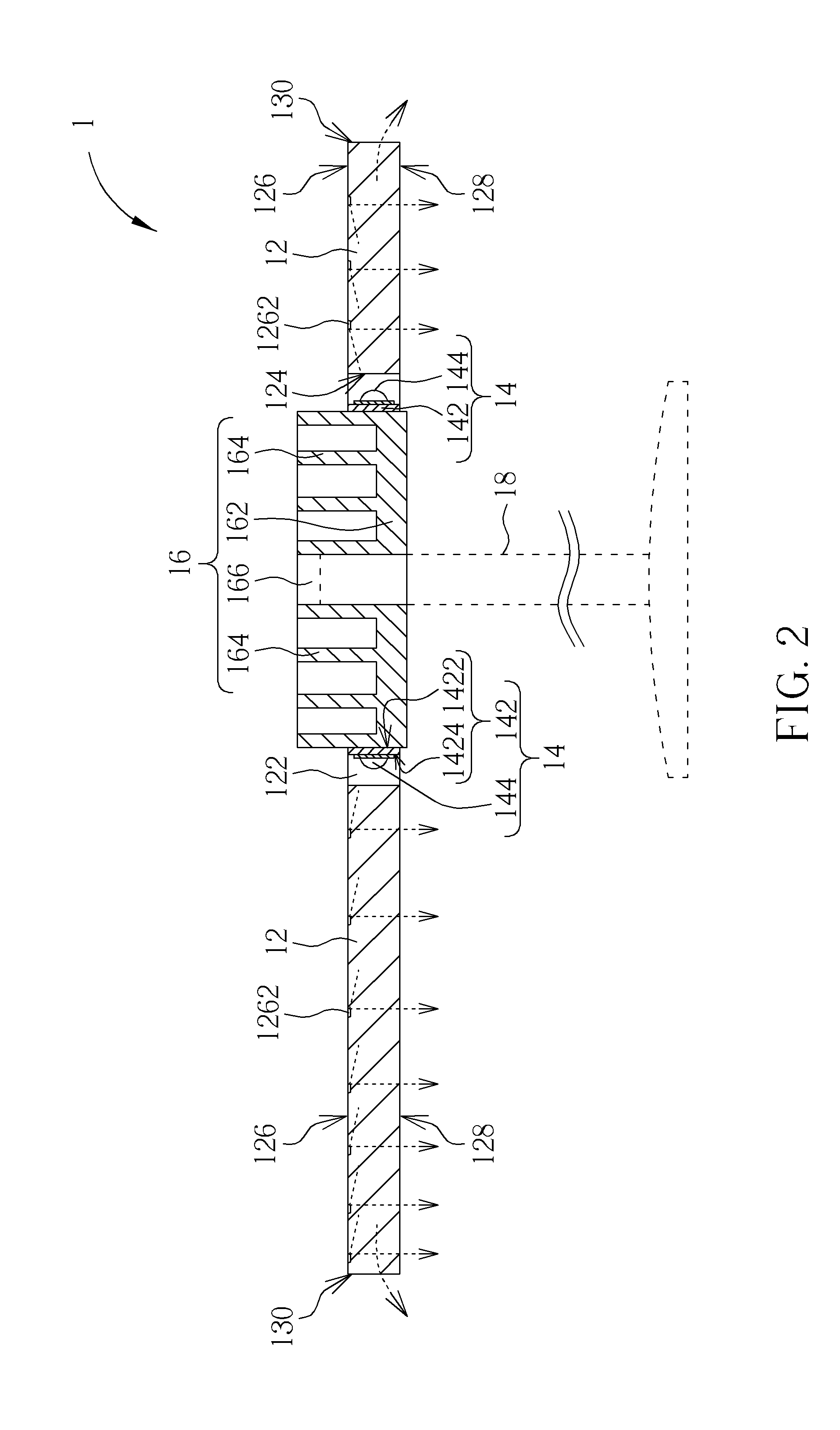
[0016]Please refer to FIG. 1 and FIG. 2. FIG. 1 is a schematic diagram of an illumination apparatus 1 of a preferred embodiment according to the present invention. FIG. 2 is a sectional view of the illumination apparatus 1 along the cutting line X-X in FIG. 1. The illumination apparatus 1 includes a light-guiding module 12, a light source module 14, and a heat-dissipating member 16. In the embodiment, the light-guiding module 12 is a light-guiding plate and has a through hole 122 having a sidewall as a light-in surface 124 of the light-guiding module 12; therefore, the light-in surface 124 is disposed inside the light-guiding module 12 and is an annular surface. The light source module 14 includes an annular circuit board 142 and a plurality of light-emitting devices 144. The annular circuit board 142 is disposed in the through hole 122 and has an inner annular surface 1422 and an outer annular surface 1424. The light-emitting devices 144 are disposed on the outer annular surface 14...


PUM


Abstract

An illumination apparatus is disclosed and includes a light-guiding module and a light source module. The light-guiding module has a light-in surface, which is annular surface inside the light-guiding module. The light source module includes a plurality of light-emitting devices. Each light-emitting device is disposed toward the light-in surface and can emit light through the light-in surface into the light-guiding module. The light-guiding module can be a light-guiding plate with a through hole, a sidewall of which is treated as the light-in surface. The light source module can use an annular circuit board disposed in the through hole. The light-emitting devices are disposed on an outer annular surface of the annular circuit board toward the sidewall. Thereby, the invention can provide illumination of radially guiding light.

Description

BACKGROUND OF THE INVENTION[0001]1. Field of the Invention[0002]The invention relates to an illumination apparatus, and especially relates to an illumination apparatus capable of providing illumination of radially guiding light.[0003]2. Description of the Prior Art[0004]As various light sources develop, the light-emitting diodes (LED) are progressively applied in the field of illumination because of the improvement in its power. To an LED illumination apparatus with a single point source, its luminance and illumination area are too limited to be illumination for reading; the bright spot due to the point source makes eyes of a user uncomfortable. In order to increase the integral luminance of the illumination apparatus, it usually uses a plurality of high power LEDs arranged in plane and additionally uses a lamp cover for properly softening the light emitted by the high power LEDs to reduce the harsh feeling due to the point sources. This configuration is conducive to increasing the ...

Claims


Application Information

Patent Timeline
Patent Type & Authority Applications(United States)
IPC IPC(8): F21V29/00G02B6/00
CPCG02B6/0021G02B6/0068G02B6/0073G02B6/0085G02B6/0091F21V2200/20F21S6/005F21Y2101/02F21Y2103/022F21V29/78F21S6/002F21Y2103/33F21Y2115/10
Inventor LIN, YU-YUAN
Owner QISDA CORP
Why Eureka
Try Eureka