Image Generation Unit and Method to Use an Image Generation Unit

Inactive Publication Date: 2008-08-28
SONY DEUT GMBH
View PDF3 Cites 35 Cited by
  • Summary
  • Abstract
  • Description
  • Claims
  • Application Information

AI Technical Summary

Benefits of technology

[0042]It is an object of the present invention to provide an image generation unit and a method to use an image generating unit, which introduce at most a

Problems solved by technology

It is a well-known problem that illumination devices and respective light sources do not only generate light in the respective channels with respective profiles and distributions but also tend to inherently produce some parasitic noise.
Such kind of laser projectors with a single scanning beam are a potential safety risk for viewers, because in case of a malfunction of the scanning mirrors a static laser beam of high intensity is projected to the screen.
These lamps have several drawbacks: As these lamps emit white light, the light must be split into the primary colours (R, G, B) by the use of filters, which add size, weight and cost to the projection system.
Moreover, light, which is not within the spectral range of the primary colours, is lost, thereby reducing the efficiency of the system.
Another drawback is the emission of IR- and UV-radiation.
The glass bulb containing the electrodes of the arc lamp has an operating temperature close to 1000° C. and consequently has to be controlled and cooled by a forced airflow, which causes annoying noise.
Light emitted by high-pressure arc lamps is unpolarized, which is a drawback when used in combination with polarizing image modulators like LCD (Liquid Crystal Display) or LCoS (Liquid Crystal on Silicon).
It is impossible to decrease the étendue of a beam by any kind of optical transformation, except the case where part

Method used


Image

  • Image Generation Unit and Method to Use an Image Generation Unit
  • Image Generation Unit and Method to Use an Image Generation Unit
  • Image Generation Unit and Method to Use an Image Generation Unit

Examples


Example

[0066]In the following functional and structural description similar or equivalent element structures will be denoted with the same reference symbols. Not in each case of their occurrence a detailed description will be repeated.

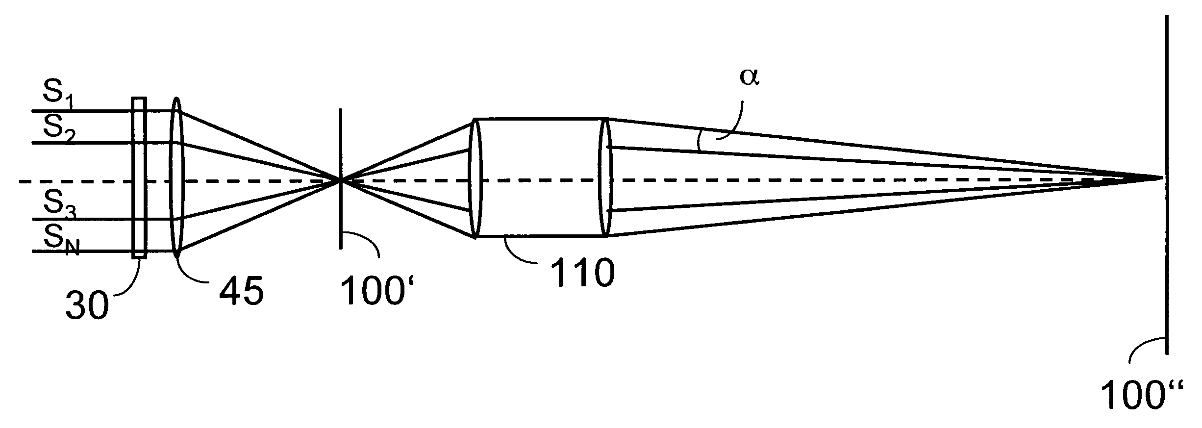
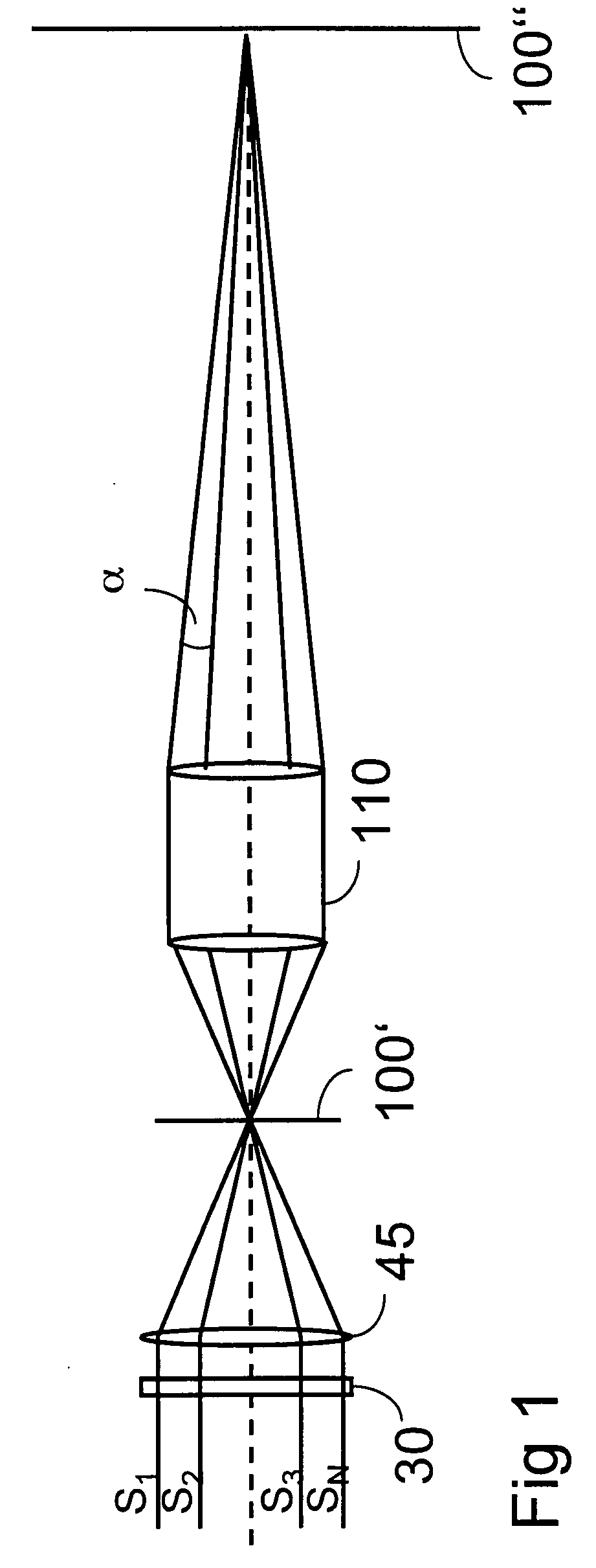
[0067]In FIG. 1 it is depicted schematically how a plurality of coherent sub-beams S1, . . . , SN are superimposed with the help of an optical imaging apparatus (here a condenser lens 45) to an image modulator 100′. The image at the image modulator 100′ is projected by the projection lens 110 to the projection screen 100″. The angles α of the projected beams of the sub-beam S1, . . . , SN are sufficiently separated, so that each of the sub-beams S1, . . . , SN will generate a different speckle pattern on the projection screen 100″ which is uncorrelated to the speckle patterns generated from the other sub-beams. The speckle pattern depends on wavelength, size and density of diffusing particles in the projection screen, thickness of the diffusing layer in the p...


PUM


Abstract

An image generation unit with an illumination unit for generating a plurality of coherent sub-beams and for illuminating an image modulator, including a light source, and a projection lens for superimposing each of the coherent sub-beams onto a projection screen plane. An optical set-up introduces angles between each two of the sub-beams, which are chosen to produce uncorrelated speckle patterns in the projection screen plane, resulting in an interference speckle pattern. A phase modulator including a liquid crystal cell changes its directory profile in a lateral manner, thereby being able to change the phase of light of each sub-beam individually.

Description

FIELD OF THE INVENTION[0001]The present invention relates to an image generation unit and a method to use an image generation unit. The present invention more particularly relates to laser illumination device providing beam shaping and speckle reduction capabilities, and image display engine using the device.BACKGROUND OF THE INVENTION[0002]Display devices become more and more important in electronic equipment and customer devices. Therefore, the technical development also focuses on processes and devices of illumination, image generation, and projection. It is a well-known problem that illumination devices and respective light sources do not only generate light in the respective channels with respective profiles and distributions but also tend to inherently produce some parasitic noise. These noise are called speckles in the field of laser light sources.[0003]Lens arrays—often in the form fly-eye lenses or integrator plates—are commonly used in projection systems in order to unifor...

Claims


Application Information

Patent Timeline
IPC IPC(8): G02F1/01
CPCH04N9/3129G02B27/48
Inventor KAMM, MARKUSRIPOLL, OLIVIER
Owner SONY DEUT GMBH
Why Eureka
Try Eureka