Anti-electricity-theft metering box and method

A metering box, anti-theft electricity technology, applied in the direction of measuring electrical variables, measuring devices, measuring time integration, etc., can solve the problems of maintenance personnel, such as hidden safety hazards, poor contact, easy loosening, etc., and achieve the goal of reducing safety hazards, convenience and maintenance Effect

Inactive Publication Date: 2021-12-28
济南宝桠商贸有限公司
View PDF0 Cites 0 Cited by
  • Summary
  • Abstract
  • Description
  • Claims
  • Application Information

AI Technical Summary

Problems solved by technology

At present, the commonly used metering boxes are all using padlocks or built-in locks. It is easy for users who steal electricity to prepare keys or pry open the door of the metering box to steal electricity. These acts of stealing electricity have caused certain economic losses to the power supply department. Many unsafe factors have been brought about, and the metering box itself does not have the anti-stealing function, which is one of the important factors that cause the user to easily steal electricity. In addition, the equipment in the metering box cannot be grounded in time after the maintenance personnel open the door, thus It has brought great safety hazards to the maintenance personnel. The existing device can realize the power failure when opening the door, and the electronic lock power supply when closing the door. However, after a long time of use, the door of the box body is easy to loosen, which may lead to poor contact. Affect power supply

Method used


Image

  • Anti-electricity-theft metering box and method
  • Anti-electricity-theft metering box and method
  • Anti-electricity-theft metering box and method

Examples


Embodiment Construction

[0030] Embodiments of the present invention are described in detail below, examples of which are shown in the drawings, wherein the same or similar reference numerals designate the same or similar elements or elements having the same or similar functions throughout. The embodiments described below by referring to the figures are exemplary only for explaining the present invention and should not be construed as limiting the present invention.

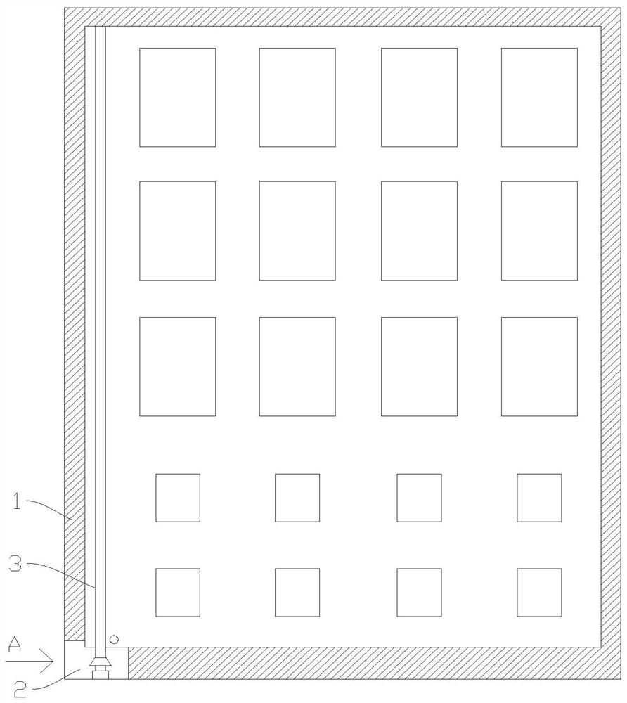
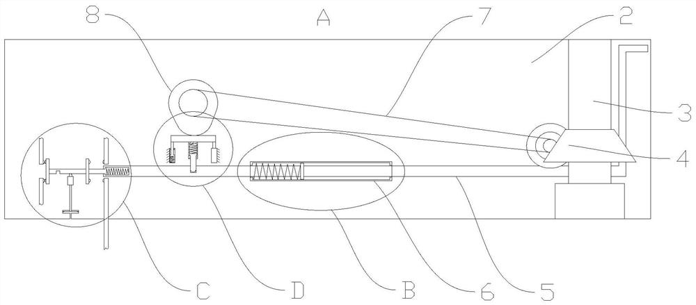
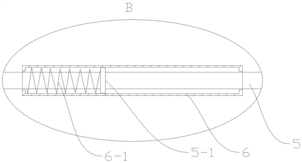
[0031] An anti-theft electrical metering box, comprising a box body 1, the box body 1 hinges the box door through a rotating shaft 3, a safety zone 2 is set on the inner side of the bottom of the box body 1, and a guide is fixed on the back of the vertical box body 1 in the safety zone 2 Pipe 6, the ejector rod 5 is slidingly arranged in the guide pipe 6, the part of the ejector rod 5 located in the guide pipe 6 is fixedly sleeved with the ring 5-1, between the ring 5-1 and the left end of the guide pipe 6 Set the first spring 6-1, the l...


PUM


Abstract

The invention discloses an anti-electricity-theft metering box and method. The anti-electricity-theft metering box comprises a box body, the box body is hinged to a box door through a rotating shaft, a safety area is arranged on the inner side of the bottom of the box body, a guide pipe is fixedly arranged in the safety area and is perpendicular to the back surface of the box body, an ejector rod is arranged in the guide pipe in a sliding mode, and a connecting rod is arranged at the left end of the ejector rod in a telescopic mode. A conductive plate and a grounding plate are arranged on the connecting rod, and conductive plate abuts against incoming paths and outgoing paths of wires leftwards so that circuits can be communicated. The rotating shaft is in transmission connection with a cam through a gear set and a belt, the cam abuts against a first clamping rod, the first clamping rod is vertically arranged on the inner wall of the safety area in a sliding mode, and the ejector rod is correspondingly provided with a first groove; and a second clamping rod driven by an electromagnetic device is arranged on one side of the connecting rod, and the electromagnetic device is activated by an electrified key to operate. The structure is reasonable and simple, the circuit is disconnected and grounded only after the box door is opened to a certain degree, power supply can be recovered only by a specific power-on key after the box door is closed, and finally the effects of electricity stealing prevention, convenience in maintenance and no influence on power-on after the box door is loosened are achieved.

Description

technical field [0001] The invention belongs to the technical field of metering box anti-theft electricity, and in particular relates to an anti-theft electricity metering box and a method. Background technique [0002] Generally, users steal electricity by opening the metering box privately and illegally operating the meter to achieve the purpose of stealing electricity. At present, the commonly used metering boxes are all using padlocks or built-in locks. It is easy for users who steal electricity to prepare keys or pry open the door of the metering box to steal electricity. These acts of stealing electricity have caused certain economic losses to the power supply department. Many unsafe factors have been brought about, and the metering box itself does not have the anti-stealing function, which is one of the important factors that cause the user to easily steal electricity. In addition, the equipment in the metering box cannot be grounded in time after the maintenance pers...

Claims


Application Information

Patent Timeline
Patent Type & Authority Applications(China)
IPC IPC(8): G01R11/04G01R11/24
CPCG01R11/04G01R11/24
Inventor 张令保
Owner 济南宝桠商贸有限公司
Why Eureka
Try Eureka