Animal injury device capable of autonomously controlling impact force

A technology of autonomous control and strength, applied in the direction of animal restraint equipment, medical science, veterinary instruments, etc., can solve the problems of uncontrollable strength, affecting the research of impact injury, and adversely affecting the treatment effect of injured patients, so as to facilitate impact experiments, improve Fixed effects, data-rich effects

Pending Publication Date: 2022-01-04
中国人民解放军陆军特色医学中心
View PDF6 Cites 0 Cited by
  • Summary
  • Abstract
  • Description
  • Claims
  • Application Information

AI Technical Summary

Problems solved by technology

[0003] In the prior art, when performing animal impact experiments, the experimenters cannot independently control the impact force through the animal injury device, so that the force suffered by the animal cannot be controlled, and it is inconvenient to obtain the damage data of the animal under different impact forces. As a result, the animal impact experiment has certain limitations, which affects the research on impact injury and is not conducive to improving the treatment effect on the injured. However, the application uses the ejection component and the elastic band, based on the problem that the impact force on the animal cannot be controlled independently, and To improve the problems raised above, the animal injury device can independently control the impact force, and enrich the data of animal impact experiments

Method used


Image

  • Animal injury device capable of autonomously controlling impact force
  • Animal injury device capable of autonomously controlling impact force
  • Animal injury device capable of autonomously controlling impact force

Examples


Embodiment 1

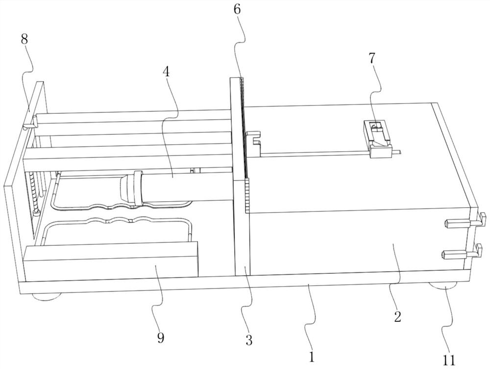
[0037] refer to figure 1 , a preferred embodiment of the present invention includes a base 1, a transmission chamber 2 is provided on the top of the base 1 and near the right side edge, and three sets of cylindrical movable chambers 21 are opened inside the transmission chamber 2, and between the movable chambers 21 Connected to each other, the top of the base 1 and the left side of the transmission compartment 2 are welded and fixed with a fixed plate 3, the interior of the transmission compartment 2 and near the left edge are provided with an impact assembly 4, and the right side of the impact assembly 4 displaces each movable chamber The interior of 21 is provided with ejection assembly 5, the right side of fixed plate 3 and is positioned at the top of transmission chamber 2 and is provided with the elastic band 6 of array distribution, and the top of transmission chamber 2 is installed with fixed assembly 7 near the edge of right side, and base A baffle 8 is welded and fix...

Embodiment 2

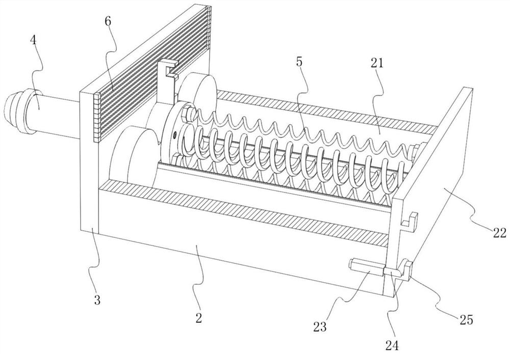
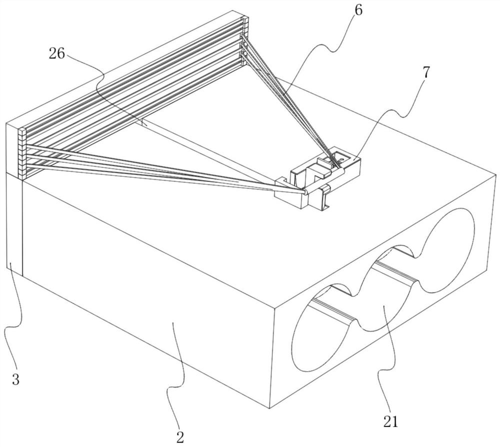
[0040] refer to Figure 2-6 , in a preferred embodiment, the right side of the transmission compartment 2 is provided with a compartment door 22, the rear side of the compartment door 22 is hinged with the side wall of the transmission compartment 2, and the front side of the transmission compartment 2 is provided with a Fixed blocks 23 parallel to each other, each fixed block 23 is provided with a movable rod 24, the movable rod 24 is connected with the fixed block 23 in rotation, the movable rod 24 is an L-shaped structure, and the right side of the door 22 is set near the front edge There are blocks 25 parallel to each other, and the movable rod 24 is engaged with the blocks 25. A chute 26 is provided on the top of the transmission chamber 2 near the left end, and the ejection assembly 5 in the movable chamber 21 is conveniently adjusted through the chamber door 22. , so as to facilitate the control of different forces for impact experiments.

[0041] In a preferred embodi...

Embodiment 3

[0047] refer to Figure 7 , in a preferred embodiment, the fixed assembly 7 includes a fixed frame 71, the fixed frame 71 is located at the rear side of the chute 26, and is welded to the top of the transmission bin 2, and the inside of the fixed frame 71 is provided with a movable frame near the front edge. Plate 72, movable plate 72 is slidably connected with fixed frame 71, the rear side of movable plate 72 is provided with the 3rd spring 73, and one end of the 3rd spring 73 is welded and fixed with fixed frame 71, and the other end of the 3rd spring 73 is connected with movable plate 72 Welding is fixed, and the front side of movable plate 72 and is positioned at the front side of chute 26 are provided with limit frame 74, and limit frame 74 is welded with the top of transmission bin 2, and movable plate 72 is clamped and matched with limit frame 74, thereby makes movable The plate 72 can limit the slider 42, so as to facilitate the control of the impact test.

[0048] In...


PUM


Abstract

The invention discloses an animal injury device capable of autonomously controlling the impact strength. The device comprises a base, wherein a transmission bin is arranged at the top of the base and close to the right side edge, a fixing plate is arranged on the left side of the transmission bin, an impact assembly is arranged in the transmission bin and close to the left side edge, ejection assemblies are arranged on the right side of the impact assembly, and elastic belts in array distribution are arranged on the right side of the fixing plate. According to the invention, the three groups of the ejection assemblies are arranged in a movable cavity, one to three groups of the ejection assemblies can be used for pushing the impact assembly to move, and the elastic force of the ejection assemblies can be adjusted by controlling the number of second springs, so that the impact strength of the impact assembly is controlled; and different numbers of the elastic bands are selected through hook-and-loop fasteners, so that the impact strength of the impact assembly can be further controlled, the impact strength can be autonomously controlled, data of animal impact experiments is enriched, and research on impact damage can be enhanced.

Description

technical field [0001] The invention belongs to the technical field of animal impact experiments, in particular to an animal injury device that can autonomously control the impact force. Background technique [0002] In real life, accidents such as traffic accidents, falling objects, and falls often cause impact injuries to the human body. Among them, visceral impact injuries, spinal cord injuries, and craniocerebral injuries have very high mortality and disability rates. A heavy burden and injury to an individual or family. In order to improve the treatment effect and reduce the mortality and disability rate of injured patients, it is necessary to strengthen the research on impact injury through a large number of animal impact experiments, so as to provide a rich data basis for improving the treatment of patients. [0003] In the prior art, when performing animal impact experiments, the experimenters cannot independently control the impact force through the animal injury d...

Claims


Application Information

Patent Timeline
Patent Type & Authority Applications(China)
IPC IPC(8): A61D1/00A61D3/00
CPCA61D1/00A61D3/00
Inventor 邱金龙秦明新刘红利周慈车兴平李奎李昊澄
Owner 中国人民解放军陆军特色医学中心
Why Eureka
Try Eureka