Water electrolysis hydrogen production device and application thereof

A hydrogen production device and water electrolysis technology, applied in the electrolysis process, electrolysis components, circuits, etc., can solve the problems of high site requirements, high surrounding environment requirements, and no better solutions, achieving simple and portable structure, solving promotion and Limitation of application, effect of promoting development

Active Publication Date: 2022-02-18
GUANGDONG INST OF NEW MATERIALS
View PDF11 Cites 0 Cited by
  • Summary
  • Abstract
  • Description
  • Claims
  • Application Information

AI Technical Summary

Problems solved by technology

However, the development of hydrogen fuel cell vehicles needs to be matched with a large number of hydrogen refueling stations. The construction cost of hydrogen refueling stations is high, the site requirements are high, and the surrounding environment is also high. As a result, there are defects in the distribution of hydrogen refueling stations, and hydrogen refueling stations cannot be built in some areas. , especially some remote and economically backward areas
Currently, there is no good solution to this problem

Method used


Image

  • Water electrolysis hydrogen production device and application thereof
  • Water electrolysis hydrogen production device and application thereof
  • Water electrolysis hydrogen production device and application thereof

Examples


Embodiment 1

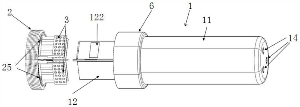
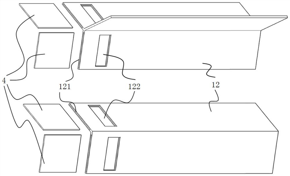
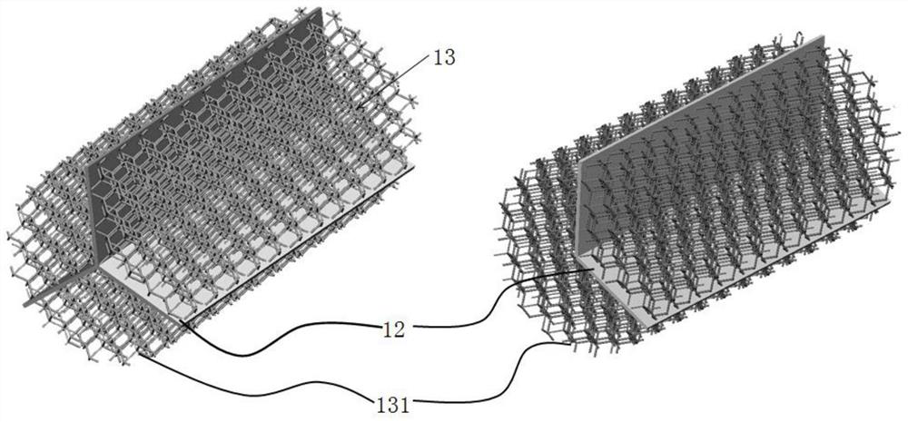
[0122] A cylindrical tank body 1 cavity is divided into Figure 4 Three equal volumes shown, made of PTFE image 3 As shown in the separator 12, the Nafion film is cut to an appropriate size, and from figure 2 The shown electrolytic diaphragm assembly port 121 is inserted into the bottom of the separator 12, and the three Figure 15 The air core 5 shown is installed into the air hole on the top of the tank 1, and then the separated tank 1 is filled with mesh polytetrafluoroethylene; two titanium electrodes coated with Pt / C and one coated with IrO 2 Titanium electrodes installed on Figure 9 On the shown tank body base 2, the tank body 1 is connected with the base, sealed and fastened, forming such as figure 1 The electrolytic cell shown.

Embodiment 2

[0124] A cylindrical tank body 1 cavity is divided into Figure 4 Three equal volumes shown, made of PTFE image 3 Shown separator 12, FAAM-PK-75 membrane (anion exchange membrane) is cut into suitable size, and from figure 2 The shown electrolytic diaphragm assembly port 121 is inserted into the bottom of the separator 12, and the three Figure 15 The air core 5 shown is put into the air hole on the top of the tank body 1, and then the separated tank body 1 is filled with mesh polyethylene; two NiMo electrodes and one nickel electrode coated with NiFeP are installed on the Figure 9 On the shown tank body base 2, the tank body 1 is connected with the base, sealed and fastened, forming such as figure 1 The electrolytic cell shown.

Embodiment 3

[0126] A cylindrical tank body 1 cavity is divided into Figure 4 Shown are two parts in a 1:2 volume ratio, made of PTFE image 3 As shown in the separator 12, the Nafion film is cut to an appropriate size, and from figure 2 The shown electrolytic diaphragm assembly port 121 is inserted into the bottom of the separator 12, and the two Figure 15 The air core 5 shown is installed into the top air hole of the tank body 1, and then the separated tank body 1 is filled with mesh polyethylene; a titanium electrode coated with Pt / C and a titanium electrode coated with IrO 2 Titanium electrodes installed on Figure 9 On the tank body base 2 shown, the tank body 1 and the base are connected, sealed and fastened to form an independent electrolysis unit.


PUM


Abstract

The invention provides a water electrolysis hydrogen production device and application thereof, and relates to the technical field of electrolysis devices. The device comprises a tank body, a tank body base, electrolysis electrodes and an electrolysis diaphragm, the tank body comprises a shell and separation sheets, and the separation sheets are arranged in the shell and divide the shell into a plurality of independent chambers, the shell is connected with the tank body base in a matched mode, a fastening groove detachable from the partition piece is formed in the tank body base, the electrolysis electrodes are installed on the tank body base, each chamber is internally provided with one electrolysis electrode correspondingly, and the tank body base is provided with power connection contacts matched with the electrolysis electrodes; an electrolytic diaphragm assembly port and an electrolytic diaphragm window are arranged at one end, close to the tank body base, of the separation sheet; the electrolytic diaphragm is inserted into the separation sheet through the electrolytic diaphragm assembly port and is in contact with the electrolyte through the electrolytic diaphragm window; a gas-liquid hole is formed in the top of the tank body, and a gas core is arranged in the gas-liquid hole. The device can be used as an emergency or daily standby gas source, and hydrogen and oxygen can be provided for gas equipment such as a hydrogen fuel cell automobile without depending on a hydrogen refueling station.

Description

technical field [0001] The invention relates to the technical field of electrolysis devices, in particular to a hydrogen production device by electrolysis of water and its application. Background technique [0002] At present, all countries in the world are facing the problems of environmental degradation and energy resource shortage to varying degrees, so it is necessary to vigorously develop clean energy technology and renewable energy technology. [0003] Hydrogen is an extremely clean energy carrier that produces only water and no other emissions during its use, so it has attracted widespread attention. There are many ways to produce hydrogen. Among them, hydrogen production by electrolysis of water is a process that only consumes electricity and water to continuously obtain high-purity hydrogen. This technology can be combined with renewable energy for large-scale and low-cost hydrogen production. The produced hydrogen can be used in power generation, metallurgy, chemi...

Claims


Application Information

Patent Timeline
Patent Type & Authority Applications(China)
IPC IPC(8): C25B1/04C25B9/19H01M8/0656
CPCC25B1/04C25B9/19H01M8/0656Y02E60/50
Inventor 刘太楷宋琛邓春明邓畅光刘敏
Owner GUANGDONG INST OF NEW MATERIALS
Why Eureka
Try Eureka